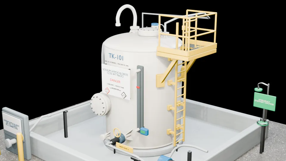
Can Fiberglass Tanks Be Repaired? The Short Answer
Many industrial fiberglass tanks can be repaired, but repairability depends on the remaining structural laminate, damage extent and cause, chemical and temperature service, tank geometry, access, and applicable requirements. A crack, blister, stain, or leak does not by itself establish the correct repair. The tank should be evaluated before a repair, reline, modification, or replacement decision is made.
What fiberglass tank repair means
An industrial FRP repair restores a defined portion of the corrosion barrier, structural laminate, connection, bottom, roof, or attachment using a documented material and laminate design. The work may be external, internal, or both. It is different from applying a consumer patch over an unexplained symptom.
A complete repair plan should address:
- the actual damage mechanism and its full extent;
- the surrounding laminate and load path;
- process chemistry, concentration, contaminants, temperature, pressure, and vacuum;
- resin, veil, reinforcement, and secondary-bond compatibility;
- substrate preparation, environmental conditions, layup, cure, and inspection;
- piping, support, foundation, venting, or operating causes outside the damaged spot;
- project-specific acceptance and return-to-service criteria.
What determines whether an FRP tank is repairable?
Repairability is an engineering and condition-assessment question. A bounded nozzle crack in otherwise sound laminate is a different problem from widespread chemical penetration, global buckling, severe foundation distortion, or catastrophic rupture. The decision normally requires some combination of drawings, service history, external and internal examination, defect mapping, material identification, and fit-for-purpose testing.
Localized and bounded damage may be repairable when the cause can be corrected and a sound substrate and load path remain. Broad corrosion-barrier degradation may be a relining candidate only when the structural laminate and bonding substrate remain suitable. Widespread structural damage, unknown construction, incompatible changed service, repeated repair failure, or inability to establish structural adequacy should trigger replacement evaluation. Applicable codes and project-specific engineering still govern the decision.
Repair, relining, modification, and replacement are different decisions
Repair addresses defined damage. Relining restores a broader internal corrosion barrier after the substrate is evaluated and structural defects are corrected. Modification changes the original configuration or load path—for example, adding a nozzle, mixer support, or reinforcement—and may require design review beyond a repair. Replacement removes an asset that cannot be shown suitable for continued or changed service.
Some projects require more than one path: a leaking nozzle can need structural reconstruction, followed by restoration of the local internal barrier; a broadly degraded interior can require isolated structural repairs before a full reline. Relining must not be used to conceal an unsuitable substrate.
What to do when a tank is actively leaking
Weeping, seepage, droplets, a stream, or a spray indicates loss of containment, but the visible opening may not show the full extent of internal or interlaminar damage. Follow the facility’s emergency, isolation, environmental, and safety procedures. Do not grind, drill, pressurize, or apply an improvised patch to an in-service industrial tank without an approved assessment and work plan.
An active leak can involve hazardous product, stored energy, a confined space, environmental reporting, secondary containment, and connected equipment. The owner’s emergency procedures and qualified site personnel control the initial response. Once facility controls are in place, contact Plastech for fiberglass tank repair support. Remember, a contractor call is not a substitute for the facility’s emergency plan.
FRP Tank Anatomy: Layers and Load Paths
An FRP tank is a laminated structure. Its internal chemical barrier, load-carrying wall, exterior surface, and secondary-bonded connections perform different functions and can fail by different mechanisms. That layered construction is why “fiberglass” cannot be evaluated as one uniform material. ASTM D3299-26 covers qualifying contact-molded and filament-wound aboveground vertical corrosion-resistant tanks within its stated scope, while ASTM C582-23 addresses qualifying contact-molded corrosion-resistant laminates.
The internal corrosion barrier
The inside surface is usually resin rich because the resin system and veil isolate glass reinforcement from the stored process. The details vary by construction standard, service, and original design.
Surfacing veil and resin-rich inner surface
The veil supports a resin-rich surface with comparatively little exposed glass. It is the first region to contact the stored chemical. Roughness, loss of gloss, pitting, crazing, veil erosion, chemical penetration, and exposed fibers often begin here.
Corrosion-barrier laminate
Behind the inner surface is a corrosion-resistant laminate designed to delay chemical access to the load-carrying structure. Its thickness, resin content, reinforcement, cure, and compatibility are service-specific. ASTM C581-26 explicitly says its unstressed laboratory results are a guide—not the sole basis for resin selection—because stress, resin-to-glass ratio, veils, and other factors affect field serviceability.
The structural laminate
The structural wall resists liquid head, pressure or vacuum within the tank’s design scope, wind, seismic and environmental loads, roof and attachment loads, nozzle loads, and local bending. It may be contact molded, filament wound, or constructed using another qualified method.
Glass reinforcement and resin matrix
Glass carries load along the reinforcement directions; cured resin transfers stress between fibers, holds the laminate geometry, and contributes chemical and environmental protection. Dry glass, voids, missing plies, incorrect fiber orientation, poor cure, or resin degradation can interrupt that load-sharing system.
Hoop, axial, bending, and local loads
Hydrostatic head mainly creates hoop and axial shell demands, but real tanks also experience bending at bottoms, knuckles, penetrations, supports, anchors, roofs, and attachments. Pipe dead load, forced fit-up, thermal movement, vibration, and valve or fitting weight can concentrate load at a nozzle even when the tank wall away from the connection appears normal.
The exterior resin-rich surface and weather barrier
The outside surface protects reinforcement from sunlight, rain, spills, abrasion, and handling. UV exposure can cause fading, chalking, roughness, resin loss, crazing, and fiber blooming. These can be important maintenance findings without automatically proving through-wall or structural failure.
Secondary bonds and reinforced openings
Nozzles, manways, repads, lugs, and repair laminates are often joined to cured parent laminate by a secondary bond. Preparation, cleanliness, taper, resin compatibility, laminate sequence, cure, geometry, and load transfer are therefore central to reliability.
Nozzles and flanges
Nozzles create an opening and stiffness transition in the shell. Their neck, flange, repad, internal fillet, external bond, gasket, bolts, and connected piping must work as a system. ASTM D5421-23 covers certain contact-molded FRP flanges but expressly does not settle flange design or gasket selection. FRPI’s What Are the Risks? FRP Flanges and Nozzles also highlights alignment, gasket selection, bolt load, piping dead load, thermal movement, creep, fatigue, and secondary-bond risks.
Manways, vents, drains, and fittings
Large manways interrupt more shell area; bottom drains see concentrated flow and bottom/knuckle interaction; vents affect pressure and vacuum safety; fittings can create local erosion, wear, and stress.
Repads, attachments, and repair laminates
Repads spread load only while their bond and substrate remain sound. A pad can lift, hollow, crack, or transfer force into the parent shell if preparation, cure, geometry, or actual service loads are unsuitable.
Tank bottom, knuckle, shell, and roof load paths
The bottom transfers liquid weight to its support. The knuckle transitions from bottom to shell and can see bending, settlement, abrasion, and chemistry simultaneously. The shell carries hydrostatic and environmental loads. The roof resists its own live and environmental loads and interacts with vents, nozzles, platforms, and mixers. A foundation, anchor, or vent problem can therefore produce damage far from its origin.
Warning Signs That Require Prompt FRP Evaluation
The most important warning signs are change, growth, loss of containment, loss of shape, and damage at a critical load path. A photograph can document an indication, but it rarely establishes its depth, mechanism, or repairability.
Weeping, seepage, droplets, streams, or spray
Any product on the outside of a closed tank is a containment concern. Map the source; do not assume the first wet point is the opening. Liquid can track beneath a patch, along a bond interface, around a gasket, or down the shell from a higher connection.
Cracks, crazing, whitening, and exposed fibers
Fine surface crazing differs from a structural crack, but both require context. Crack orientation, length, depth, growth, position, and relationship to loads matter. Whitening can reflect fiber/matrix interface damage or strain; fiber blooming can reflect exterior weathering. Neither sign alone confirms whether the tank is safe or repairable.
Blisters, bubbles, soft laminate, or delamination
Raised blisters can contain fluid or gas and occur at different laminate interfaces. A hollow response can suggest delamination. Softness can result from cure condition, chemical absorption, heat, or degradation. Each needs area, depth, distribution, and surrounding-condition assessment.
Nozzle, flange, manway, or gasket leakage
Connection leaks may begin with sealing problems, but misalignment, pipe load, flange damage, neck cracking, or bond failure can be the underlying cause. Replacing a gasket without evaluating a distorted or cracked FRP connection can leave the initiating load in place.
Bulging, buckling, out-of-roundness, or settlement
Loss of geometry can indicate creep, hydrostatic or pressure overload, vacuum instability, insufficient stiffness, foundation movement, or poor support. Measure the geometry and inspect connected piping, nozzles, anchors, bottom, knuckle, and roof rather than isolating the visible bulge.
Damaged, discolored, or repeatedly failing prior repairs
A failed patch or reline may reveal incompatible material, insufficient preparation or cure, a contaminated or unsound substrate, damage beyond the repair perimeter, or an uncorrected load. The old repair should be treated as part of the evidence, not automatically covered by another layer.
Conditions that may require shutdown or emergency procedures
Active product release, rapid crack growth, nozzle separation, major deformation, vacuum collapse, overpressure damage, fire exposure, foundation failure, severe anchor damage, or suspected catastrophic instability may require the tank to remain out of service pending qualified evaluation. The decision belongs within the facility’s emergency, EHS, operating, and engineering controls.
Fiberglass Tank Failure and Damage Guide
The guide below covers 53 external and 46 internal FRP tank conditions, from commonly encountered inspection findings to less common, high-consequence failures. Use the descriptions to recognize warning signs and prepare better inspection questions; a qualified assessment is still needed to confirm the condition and the appropriate response.
How the entries are ranked—and how to read them
The entries are ordered from conditions more commonly encountered in FRP inspection and maintenance literature to less common or catastrophic outcomes. The order is practical guidance, not a statistical industry incident rate. Frequency and severity are different: a common stain may be superficial, while a less common rupture can be catastrophic.
The entries deliberately separate:
- indication — what can be observed;
- defect or damage — what examination establishes;
- mechanism — why it developed;
- outcome — such as leakage, collapse, or rupture;
- disposition — repair, reline, modify, monitor, or replace;
- fitness for service — an asset-specific engineering conclusion.
No item below is a remote diagnosis, acceptance criterion, or repair specification.
External FRP Tank Failure Modes
Exterior surface and weathering failures
Weathering and visual-condition indicators
External condition
Exterior discoloration, staining, and loss of gloss
CategoryExterior surface condition.

- What you may notice
- Color change, streaks, deposits, or dull patches indicate exposure or aging but do not prove structural damage.
- Common causes and contributors
- UV, weather, spills, permeation, heat, and process vapors.
- Why it matters
- Deposits can conceal deeper deterioration.
- What an inspection should confirm
- Whether the change is superficial, chemically active, or associated with softness, cracking, or fiber exposure.
External condition
UV degradation, chalking, and exterior resin weathering
CategoryExterior surface condition.

- What you may notice
- Fading, powdery chalk, roughness, and shallow cracks develop in the resin-rich exterior.
- Common causes and contributors
- Sunlight, weather, and prolonged outdoor exposure.
- Why it matters
- Progressive resin loss can expose reinforcement.
- What an inspection should confirm
- Degradation depth, fiber condition, cracking, and whether structural laminate is involved.
External condition
Fiber blooming, fiber prominence, and exposed glass
CategoryExterior surface condition.

- What you may notice
- White, threadlike glass becomes visible or raised as surface resin recedes or microcracks.
- Common causes and contributors
- Weathering, UV, strain, resin erosion, and local stress.
- Why it matters
- Exposed reinforcement has reduced environmental protection, although blooming alone is not a through-wall failure.
- What an inspection should confirm
- Whether fibers are merely prominent or chemically, mechanically, or structurally damaged.
External condition
External crazing and fine surface cracking
CategoryExterior surface condition.

- What you may notice
- A network of fine hairline cracks appears in the exterior resin surface.
- Common causes and contributors
- UV aging, thermal cycling, strain, chemical exposure, and localized stress.
- Why it matters
- Crazing can remain superficial or become an entry path for moisture and further deterioration.
- What an inspection should confirm
- Crack depth, distribution, growth, and relation to loads or chemical exposure.
Nozzle and flange failures
Connections, sealing, and load transfer
External condition
Nozzle-to-shell bond cracking
CategoryNozzles, flanges, and load transfer.

- What you may notice
- Curved or radial cracks form at the nozzle fillet, secondary bond, or shell transition.
- Common causes and contributors
- Pipe load, thermal movement, vibration, stress concentration, and bond workmanship.
- Why it matters
- Cracking can weaken the connection and develop into leakage or separation.
- What an inspection should confirm
- Circumferential extent, depth, bond integrity, surrounding shell condition, and imposed piping loads.
External condition
Nozzle-neck cracking
CategoryNozzles, flanges, and load transfer.

- What you may notice
- Axial, circumferential, or localized cracks develop in the exposed nozzle neck.
- Common causes and contributors
- Piping dead load, misalignment, thermal expansion, vibration, impact, and insufficient laminate.
- Why it matters
- The neck carries piping and containment loads and may leak or fracture as damage grows.
- What an inspection should confirm
- Crack depth, fiber involvement, nozzle geometry, and connected-system loads.
External condition
Nozzle weeping or leakage
CategoryNozzles, flanges, and containment.

- What you may notice
- Dampness, droplets, or a narrow liquid trail appears at the neck, repad, flange, or shell bond.
- Common causes and contributors
- Cracks, porosity, chemical deterioration, or deficient bonding.
- Why it matters
- Any weep is a loss-of-containment indication and may conceal wider laminate damage.
- What an inspection should confirm
- Exact leak path, chemical exposure, damaged area, remaining laminate, and connection loads.
External condition
Flange leakage
CategoryNozzles, flanges, and containment.

- What you may notice
- Wetness or droplets emerge between mating flange faces.
- Common causes and contributors
- Lost gasket compression, misalignment, damaged faces, incorrect bolt loading, or flange cracking.
- Why it matters
- Leakage can expose the flange, nozzle, shell, and nearby equipment to chemical attack.
- What an inspection should confirm
- Face condition, flatness, gasket compatibility, bolt condition, alignment, and laminate integrity.
External condition
Flange-face damage and non-flatness
CategoryNozzles and flanges.

- What you may notice
- Scratches, chips, cracks, warpage, or an uneven mating gap interferes with gasket seating.
- Common causes and contributors
- Chemical attack, handling damage, bolt loading, creep, and fabrication variation.
- Why it matters
- An uneven face can prevent reliable sealing and concentrate bolt load.
- What an inspection should confirm
- Damage depth, flatness, gasket contact, bolt pattern, and hub condition.
External condition
Flange laminate cracking or delamination
CategoryNozzles and flanges.

- What you may notice
- Cracks or separated laminate plies appear in the ring, hub, neck, or transition.
- Common causes and contributors
- Bolt load, piping load, creep, fatigue, and deficient fabrication.
- Why it matters
- The flange may lose sealing stiffness or structural continuity.
- What an inspection should confirm
- Ply separation, crack depth, affected circumference, bolt-seat damage, and connected piping loads.
External condition
Improper bolt-torque damage or leakage
CategoryNozzles and flanges.

- What you may notice
- FRP is crushed or radially cracked below a washer, a gasket is extruded, or compression is visibly uneven.
- Common causes and contributors
- Over-torque, under-torque, uneven tightening, unsuitable hardware, or poor fit-up.
- Why it matters
- Local crushing reduces flange capacity while uneven compression defeats the seal.
- What an inspection should confirm
- Bolt loading, gasket condition, flange-face damage, laminate crushing, and alignment.
External condition
Flange misalignment and forced fit-up
CategoryNozzles, flanges, and load transfer.

- What you may notice
- Pipe and nozzle axes are offset, flange faces meet unevenly, or the pipe appears pulled into position.
- Common causes and contributors
- Installation error, support movement, settlement, or thermal displacement.
- Why it matters
- Forced fit-up imposes sustained bending and axial stress on the nozzle and shell.
- What an inspection should confirm
- Actual alignment, support condition, displacement source, bond damage, and allowable loads.
External condition
Connected-pipe dead-load damage at nozzles
CategoryNozzles and load transfer.

- What you may notice
- A nozzle sags or distorts, often with whitening or cracking near the loaded side of its bond.
- Common causes and contributors
- Unsupported pipe, valves, fittings, or concentrated equipment weight.
- Why it matters
- Sustained load can cause creep, cracking, bond failure, or nozzle separation.
- What an inspection should confirm
- Pipe support, imposed forces, permanent deformation, crack depth, and surrounding shell condition.
External condition
Thermal-expansion load damage at nozzles
CategoryNozzles and load transfer.

- What you may notice
- Directional nozzle displacement, opposing bond cracks, or localized stress whitening indicates restrained movement.
- Common causes and contributors
- Piping growth or contraction, inadequate flexibility, and restrictive supports or anchors.
- Why it matters
- Repeated or sustained thermal load can fatigue the nozzle and shell bond.
- What an inspection should confirm
- Operating temperature range, movement direction, restraint system, crack depth, and nozzle capacity.
External condition
Vibration and fatigue damage at nozzles or attachments
CategoryConnections and cyclic loading.

- What you may notice
- Multiple short, similarly oriented cracks or a whitening halo develops around a nozzle or attachment.
- Common causes and contributors
- Pumps, mixers, rotating equipment, agitation, and flow-induced vibration.
- Why it matters
- Repeated loading can progressively grow matrix cracks, delamination, and bond damage.
- What an inspection should confirm
- Vibration source, frequency and history, crack growth, delamination, and load path.
External chemical and mechanical damage
Exposure, surface loss, impact, and shell cracking
External condition
External chemical attack from spills, overflow, or vapors
CategoryExterior chemical exposure.

- What you may notice
- A spill path shows bleaching, roughness, softened gloss, resin loss, or exposed fibers.
- Common causes and contributors
- Overflow, leaks, washdown, process vapors, and incompatible chemicals.
- Why it matters
- External exposure can degrade structural laminate, attachments, base areas, and connected piping.
- What an inspection should confirm
- Chemical identity, concentration, exposure duration, affected depth, and fiber condition.
External condition
Surface scratches, gouges, cuts, and grinding damage
CategoryExternal mechanical damage.

- What you may notice
- Linear scratches or localized gouges remove smooth resin and may reveal pale reinforcement.
- Common causes and contributors
- Tools, access work, handling, rigging, and maintenance.
- Why it matters
- Cut fibers or lost resin protection can create a stress concentration and exposure path.
- What an inspection should confirm
- Depth, fiber severance, location, wall thickness, and any hidden delamination.
External condition
Impact damage, indentation, and crushing
CategoryExternal mechanical damage.

- What you may notice
- A dent, white stress halo, radial cracks, or crushed surface marks a concentrated impact.
- Common causes and contributors
- Vehicles, dropped objects, rigging, ladders, and equipment contact.
- Why it matters
- Subsurface delamination may extend beyond the visible mark.
- What an inspection should confirm
- Impact extent, delamination, fiber fracture, residual shape, and remaining laminate.
External condition
External matrix cracking and larger shell cracks
CategoryShell laminate damage.

- What you may notice
- A distinct crack extends beyond fine surface crazing and may branch across the shell.
- Common causes and contributors
- Load, aging, impact, settlement, thermal cycling, or inadequate laminate.
- Why it matters
- A larger crack can connect to delamination, fiber damage, or leakage.
- What an inspection should confirm
- Depth, length, orientation, growth, fiber involvement, and initiating load.
Delamination, secondary-bond, manway, and prior-repair failures
Separation at interfaces and reinforced openings
External condition
External delamination and hollow areas
CategoryShell laminate damage.

- What you may notice
- A subtly raised, whitened, or hollow-sounding area indicates separation between laminate plies.
- Common causes and contributors
- Impact, fatigue, poor cure, water entry, and fabrication defects.
- Why it matters
- Visible surface change may understate the separated area and reduced load transfer.
- What an inspection should confirm
- Delamination perimeter, depth, interfaces, moisture, and structural significance.
External condition
Repad or secondary-laminate disbonding
CategorySecondary bonds and attachments.

- What you may notice
- An edge lifts from a nozzle pad, manway pad, lug overlay, platform pad, or repair laminate.
- Common causes and contributors
- Poor preparation, contamination, cure problems, and cyclic load.
- Why it matters
- The attachment may no longer transfer load as intended.
- What an inspection should confirm
- Bonded area, substrate condition, load path, cure history, and cause of separation.
External condition
Manway-neck and manway-to-shell cracking
CategoryManways and penetrations.

- What you may notice
- Curved or radial cracks appear at the manway neck, fillet, or shell transition.
- Common causes and contributors
- Access loading, bolting, deformation, field installation, and weak secondary bonding.
- Why it matters
- The opening interrupts shell continuity and can develop leakage or local structural failure.
- What an inspection should confirm
- Crack depth, bond extent, shell deformation, flange loading, and access-related damage.
External condition
Manway flange, cover, gasket, or fastener leakage
CategoryManways and containment.

- What you may notice
- Wetness emerges at the cover gasket, often near unevenly seated bolts or an extruded gasket.
- Common causes and contributors
- Warpage, cracked laminate, incompatible gasket, uneven tightening, and damaged hardware.
- Why it matters
- Leakage exposes a large opening and adjacent shell to chemical attack.
- What an inspection should confirm
- Cover and flange geometry, gasket compatibility, bolt loading, cracks, and neck condition.
External condition
Repair-patch or external-overlaminate failure
CategoryPrior repair failure.

- What you may notice
- A previous patch cracks, peels, blisters, lifts, or differs sharply from the surrounding laminate.
- Common causes and contributors
- Unresolved root cause, incompatible materials, poor preparation, deficient cure, or damage beyond the patch.
- Why it matters
- The repair may conceal continuing deterioration or transfer stress to adjacent laminate.
- What an inspection should confirm
- Original damage, substrate condition, compatibility, bond extent, and present loads.
Fabrication and cure defects
Wet-out, consolidation, contamination, and geometry
External condition
Dry glass and incomplete wet-out
CategoryFabrication and laminate quality.

- What you may notice
- Cloudy white or opaque reinforcement remains visibly under-saturated with resin.
- Common causes and contributors
- Inadequate resin application or poor consolidation during fabrication or repair.
- Why it matters
- The area has reduced chemical protection and interlaminar continuity.
- What an inspection should confirm
- Size, depth, ply location, surface connectivity, and structural or barrier significance.
External condition
Voids, air pockets, porosity, and bubbles
CategoryFabrication and laminate quality.

- What you may notice
- Small subsurface cavities or larger irregular air pockets interrupt an otherwise continuous laminate.
- Common causes and contributors
- Entrapped air, incomplete consolidation, and unfilled spaces.
- Why it matters
- Voids reduce continuity and may seed moisture entry, blistering, delamination, or leakage.
- What an inspection should confirm
- Size, density, depth, interfaces, and connection to either surface.
External condition
Resin-starved or resin-rich areas
CategoryFabrication and laminate quality.

- What you may notice
- A matte, fiber-prominent region lies beside a glossy or amber resin pocket, sometimes with shrinkage cracks.
- Common causes and contributors
- Nonuniform resin-to-glass ratio and poor consolidation.
- Why it matters
- Starved zones expose reinforcement; resin-rich zones can be brittle and glass-deficient.
- What an inspection should confirm
- Area, depth, reinforcement content, cracking, and effect on barrier or structural performance.
External condition
Wrinkles, bridging, waviness, and fiber distortion
CategoryFabrication and laminate quality.

- What you may notice
- Raised folds, bridged hollows, or distorted fiber paths interrupt smooth laminate geometry.
- Common causes and contributors
- Misplaced reinforcement and poor consolidation.
- Why it matters
- The condition can create resin pockets, thin zones, weak directions, and stress concentrations.
- What an inspection should confirm
- Ply distortion, thickness, voiding, affected area, and load orientation.
External condition
Foreign inclusions or laminate contamination
CategoryFabrication and bond quality.

- What you may notice
- Dirt, moisture, wax, dust, or another inclusion is trapped beneath resin, sometimes with a discolored halo or nearby voids.
- Common causes and contributors
- Contaminated fabrication or repair surfaces.
- Why it matters
- Contamination can reduce adhesion, cure quality, and durability.
- What an inspection should confirm
- Material, size, depth, interface, and whether a bond or structural ply is interrupted.
External condition
Improper cure, low hardness, or exterior softness
CategoryCure and material condition.

- What you may notice
- Uneven gloss, amber color, softness, impressions, burn discoloration, shrinkage cracks, or voids indicate abnormal cure.
- Common causes and contributors
- Undercure or excessive exotherm.
- Why it matters
- The laminate may have inadequate chemical or mechanical properties.
- What an inspection should confirm
- Affected depth and area, hardness pattern, resin condition, service exposure, and associated cracking or delamination.
External condition
Uneven thickness, thin laminate, or missing reinforcement
CategoryFabrication and structural capacity.

- What you may notice
- Local depressions or geometry changes may mark a thin area or absent reinforcement.
- Common causes and contributors
- Fabrication variation, missing plies, or inadequate consolidation.
- Why it matters
- Local capacity and stiffness may fall below the intended load path.
- What an inspection should confirm
- Actual thickness, ply content, affected dimensions, design loads, and deformation.
External condition
Print-through, waviness, and geometric irregularity
CategorySurface and fabrication condition.

- What you may notice
- Fiber patterns, ripples, or low-amplitude geometry become visible under glancing light.
- Common causes and contributors
- Shrinkage, laminate pattern, consolidation, and fabrication geometry.
- Why it matters
- The condition may be cosmetic or may accompany local thinness or load concentration.
- What an inspection should confirm
- Whether thickness, stiffness, bonding, or structural shape is affected.
Deformation and fatigue failures
Time-dependent and cyclic structural damage
External condition
Shell deformation, bulging, and out-of-roundness
CategoryGlobal structural condition.

- What you may notice
- A broad shell quadrant moves outward or loses cylindrical geometry.
- Common causes and contributors
- Hydrostatic load, creep, pressure, inadequate stiffness, poor support, and fabrication shape.
- Why it matters
- Deformation redistributes load to nozzles, attachments, and adjacent laminate.
- What an inspection should confirm
- Geometry, progression, pressure history, support, wall construction, cracks, and delamination.
External condition
Creep deformation
CategoryGlobal structural condition.

- What you may notice
- Permanent sagging or smooth long-term bulging appears near sustained shell, nozzle, attachment, or roof loads.
- Common causes and contributors
- Continuous hydrostatic or external loads and time-dependent resin behavior.
- Why it matters
- Increasing strain can precede cracking, delamination, or rupture.
- What an inspection should confirm
- Deformation history, sustained loads, temperature, laminate condition, and residual geometry.
External condition
Mechanical or thermal fatigue cracking
CategoryCyclic structural damage.

- What you may notice
- Families of short cracks grow near a repeatedly loaded nozzle, attachment, roof transition, or shell zone.
- Common causes and contributors
- Filling cycles, wind, vibration, agitation, pressure, and temperature cycling.
- Why it matters
- Damage can continue below the visible surface and enlarge with each cycle.
- What an inspection should confirm
- Load history, crack growth, delamination, fiber condition, and affected stress path.
Foundation, anchor, support, and attachment failures
Support conditions and concentrated loads
External condition
Foundation settlement and tank tilt
CategoryFoundation and support.

- What you may notice
- The tank leans, one knuckle is compressed, a base gap opens, or piping becomes misaligned.
- Common causes and contributors
- Differential settlement or foundation movement.
- Why it matters
- Settlement overloads the bottom, knuckle, anchors, nozzles, and connected piping.
- What an inspection should confirm
- Tank geometry, foundation condition, bottom support, anchor loads, and secondary laminate damage.
External condition
Bottom-support voids or foundation irregularity
CategoryFoundation and support.

- What you may notice
- A localized base gap, washout, debris point, or missing support permits bottom flexure.
- Common causes and contributors
- Missing grout, pad erosion, uneven support, and trapped debris.
- Why it matters
- Concentrated bottom and knuckle stresses can create cracks or delamination.
- What an inspection should confirm
- Full support profile, bottom deformation, knuckle damage, foundation drainage, and settlement.
External condition
Anchor-lug or hold-down damage
CategoryAnchors and supports.

- What you may notice
- Cracked overlays, lifted lug laminates, elongated holes, or damaged bolts appear at a hold-down.
- Common causes and contributors
- Wind, seismic load, buoyancy, pressure, and restraint concentration.
- Why it matters
- Anchor failure can damage the parent shell or permit tank movement.
- What an inspection should confirm
- Anchor design, load history, bolt condition, overlay bond, shell damage, and foundation attachment.
External condition
Ladder, platform, handrail, mixer, and roof-attachment damage
CategoryAttachments and local load transfer.

- What you may notice
- Indentation, whitening, cracks, or shifted pads appear around an attachment.
- Common causes and contributors
- Concentrated weight, access loads, vibration, and cyclic equipment movement.
- Why it matters
- Attachment loads can crack the pad and underlying shell or roof.
- What an inspection should confirm
- Actual load path, hardware stability, bond condition, crack depth, and parent-laminate damage.
External condition
Corroded, loose, or failed metallic attachments and hardware
CategoryAttachments and hardware.

- What you may notice
- Metal bolts, clips, supports, or ladder parts show corrosion, looseness, or failure, sometimes staining the FRP.
- Common causes and contributors
- Environment, chemicals, incompatible hardware, and inadequate maintenance.
- Why it matters
- Failed hardware can lose function or impose point loads and abrasion on the composite.
- What an inspection should confirm
- Metal loss, remaining attachment function, FRP contact damage, and load transfer.
Pressure, vacuum, and roof failures
Instability and global deformation
External condition
Shell buckling or wrinkling
CategoryGlobal structural instability.

- What you may notice
- Broad circumferential or localized folds alternate inward and outward in the shell.
- Common causes and contributors
- Vacuum, wind, handling, settlement, and uneven restraint.
- Why it matters
- Buckling indicates loss of geometric stability and may damage multiple laminate layers.
- What an inspection should confirm
- Cause, residual shape, cracking, delamination, stiffness, and affected circumference.
External condition
Vacuum buckling or implosion
CategoryPressure/vacuum failure.

- What you may notice
- The upper shell or roof is pulled inward with broad concave deformation and buckle ridges.
- Common causes and contributors
- Blocked or undersized venting, rapid pump-out, cooling, or steam condensation.
- Why it matters
- Global collapse can damage shell, roof, nozzles, and laminate interfaces simultaneously.
- What an inspection should confirm
- Venting event, full deformation, cracking, delamination, and remaining structural geometry.
External condition
Overpressure bulging and cracking
CategoryPressure/vacuum failure.

- What you may notice
- The upper shell or roof bulges outward and may crack around transitions or fittings.
- Common causes and contributors
- Air loading, blocked venting, gas generation, or process upset.
- Why it matters
- An atmospheric or low-pressure tank may have exceeded its intended load capability.
- What an inspection should confirm
- Pressure event, venting, deformation, crack and fiber damage, and global tank geometry.
External condition
Roof cracking or collapse
CategoryRoof and global structure.

- What you may notice
- A roof depression, radial cracking, or displaced fitting indicates localized or broad roof failure.
- Common causes and contributors
- Vacuum, live loads, UV degradation, attachments, and inadequate design.
- Why it matters
- Roof damage can compromise venting, openings, weather protection, and shell-transition loads.
- What an inspection should confirm
- Crack depth, deformation, attachments, roof-support design, and shell-joint condition.
Environmental and extreme-event failures
Wind, water, freezing, heat, and seismic loading
External condition
Wind damage
CategoryEnvironmental and global loading.

- What you may notice
- Directional shell or roof buckling, strained anchors, or displaced attachments follows a wind event.
- Common causes and contributors
- Strong wind, inadequate anchorage, empty-tank condition, and exposed attachments.
- Why it matters
- Damage can affect the tank, anchors, foundation, roof, and piping as one system.
- What an inspection should confirm
- Alignment, shell and roof damage, anchor loads, foundation condition, and connected piping.
External condition
Uplift or flotation
CategoryEnvironmental and foundation loading.

- What you may notice
- The base lifts, anchors stretch or fail, and lower piping moves out of alignment.
- Common causes and contributors
- Floodwater, groundwater, an empty tank, or insufficient anchorage.
- Why it matters
- Uplift can damage the bottom, knuckle, anchors, nozzles, and piping simultaneously.
- What an inspection should confirm
- Bottom shape, anchor and foundation condition, piping displacement, and hidden laminate damage.
External condition
Freeze damage
CategoryEnvironmental and localized pressure.

- What you may notice
- A nozzle, drain, jacket, or low point bulges or splits, sometimes with a crack into adjacent laminate.
- Common causes and contributors
- Trapped liquid and freezing expansion.
- Why it matters
- Local expansion can fracture a connection or create a through-wall path.
- What an inspection should confirm
- Full crack extent, trapped-volume location, surrounding laminate, and recurring freeze exposure.
External condition
Fire, heat, charring, or thermal decomposition
CategoryThermal damage.

- What you may notice
- Tan-to-black discoloration, charring, blistered resin, distortion, or exposed fibers follows external heat.
- Common causes and contributors
- Fire, hot equipment, radiant heat, and abnormal temperature exposure.
- Why it matters
- Resin properties and laminate bonds can be lost beyond the visible charred area.
- What an inspection should confirm
- Temperature exposure, damage depth and area, softness or embrittlement, delamination, and fiber condition.
External condition
Seismic damage
CategoryEnvironmental and global loading.

- What you may notice
- Tank shift, anchor cracking, knuckle whitening, and nozzle or piping misalignment occur in a common direction.
- Common causes and contributors
- Earthquake acceleration and interaction among tank, contents, foundation, restraints, and piping.
- Why it matters
- Multiple components can be damaged even when the shell remains standing.
- What an inspection should confirm
- Global alignment, bottom, anchors, shell, roof, nozzles, attachments, and piping.
External loss-of-containment outcomes
Severe connection, shell, and bottom failure
External condition
Nozzle pullout or separation
CategorySevere connection failure.

- What you may notice
- The nozzle bond opens or the connection partially separates, exposing layered FRP edges and radial shell cracks.
- Common causes and contributors
- Severe pipe load, impact, deficient bonding, and progressive cracking.
- Why it matters
- Structural continuity and containment at the penetration are substantially reduced.
- What an inspection should confirm
- Surrounding shell damage, separation extent, remaining bond, pipe loads, and chemical exposure.
External condition
Through-wall shell crack or active shell leak
CategoryContainment failure.

- What you may notice
- Seepage, a stream, or spray emerges from a crack that crosses the corrosion barrier and structural wall.
- Common causes and contributors
- Chemical deterioration, load, impact, fatigue, or progressive laminate damage.
- Why it matters
- The tank has lost containment and may have broader unseen damage.
- What an inspection should confirm
- Safe isolation, crack extent, surrounding wall condition, root cause, and remaining structural capacity.
External condition
Creep rupture or catastrophic shell rupture
CategoryCatastrophic containment failure.

- What you may notice
- A large irregular opening with peeled laminate plies and broken fibers follows rapid structural separation.
- Common causes and contributors
- Sustained load, progressive damage, or an upset that exceeds remaining capacity.
- Why it matters
- Major containment and structural integrity are lost.
- What an inspection should confirm
- Event cause, full tank damage, foundation and connection effects, and whether any structure remains reusable.
External condition
Bottom blowout
CategoryCatastrophic containment failure.

- What you may notice
- The bottom or bottom-to-shell joint separates, often with failed anchors and a major release at the base.
- Common causes and contributors
- Severe structural loss, anchor-system failure, support problems, or an upset.
- Why it matters
- The primary load-carrying and containment boundary has failed.
- What an inspection should confirm
- Bottom, knuckle, anchors, foundation, shell distortion, event sequence, and surrounding equipment.
Internal FRP Tank Failure Modes
Inner-surface and corrosion-barrier degradation
Resin, chemistry, permeability, and surface wear
Internal condition
Inner-surface resin attack and normal-to-abnormal resin degradation
CategoryInternal surface and corrosion barrier.

- What you may notice
- The resin-rich surface becomes dull, rough, soft, discolored, or locally depleted; normal aging must be separated from progressive damage.
- Common causes and contributors
- Chemical service, temperature, oxidizers, vapor exposure, and time.
- Why it matters
- The corrosion barrier is the first protection for the structural laminate.
- What an inspection should confirm
- Exposure history, affected depth and area, material change, and progression.
Internal condition
Chemical attack of the corrosion barrier
CategoryInternal surface and corrosion barrier.

- What you may notice
- Whitening, amber discoloration, roughness, pitting, or softening spreads through the veil and resin-rich liner.
- Common causes and contributors
- Incompatible chemistry, concentration, temperature, oxidizers, and vapor conditions.
- Why it matters
- Continued attack can reach structural laminate.
- What an inspection should confirm
- Chemical compatibility, operating history, barrier thickness, attack depth, and fiber exposure.
Internal condition
Permeation and chemical absorption
CategoryInternal surface and corrosion barrier.

- What you may notice
- Diffuse discoloration, subsurface darkening, swelling, softness, or blistering indicates fluid or vapor movement into resin.
- Common causes and contributors
- Chemical exposure, temperature, resin characteristics, and time.
- Why it matters
- Damage can extend beyond visible surface change.
- What an inspection should confirm
- Penetration depth, material-property change, affected area, chemical service, and structural involvement.
Internal condition
Veil erosion
CategoryInternal surface and corrosion barrier.

- What you may notice
- The smooth surfacing veil is worn away, revealing coarser glass texture below.
- Common causes and contributors
- Flow, sediment, cleaning, chemical exposure, and local turbulence at bottoms, knuckles, and drains.
- Why it matters
- Loss of veil reduces the resin-rich protective layer.
- What an inspection should confirm
- Remaining barrier thickness, exposed reinforcement, affected area, and active erosion source.
Internal condition
Corrosion-barrier thinning, erosion, or washout
CategoryInternal surface and corrosion barrier.

- What you may notice
- A worn channel or broad shallow area shows reduced liner thickness toward the structural laminate.
- Common causes and contributors
- Flow, solids, cleaning, chemical attack, and oxidation.
- Why it matters
- Remaining chemical protection and service margin are reduced.
- What an inspection should confirm
- Residual barrier, structural-wall involvement, full extent, and continuing exposure.
Internal condition
Internal discoloration, staining, deposits, and loss of gloss
CategoryInternal surface and corrosion barrier.

- What you may notice
- Liquid-level rings, streaks, crystalline deposits, or dull zones record service exposure but may conceal the substrate.
- Common causes and contributors
- Process chemistry, aging, sediment, evaporation, and residual contamination.
- Why it matters
- Visual appearance alone cannot establish remaining strength, and deposits may mask damage.
- What an inspection should confirm
- Condition after safe cleaning, substrate hardness and texture, cracking, and exposure history.
Crazing, blistering, cracking, and delamination
Surface cracks, blisters, and localized resin loss
Internal condition
Crazing and fine inner-surface cracks
CategoryInternal surface and corrosion barrier.

- What you may notice
- Dense networks of hairline cracks remain at or near the resin-rich surface.
- Common causes and contributors
- Strain, chemical attack, thermal cycling, shrinkage, and local geometry.
- Why it matters
- Crazing can become a pathway for deeper chemical entry.
- What an inspection should confirm
- Crack depth, distribution, growth, chemical exposure, and underlying laminate condition.
Internal condition
Osmotic, chemical, gas, or vapor blistering
CategoryInternal surface and corrosion barrier.

- What you may notice
- Intact rounded or elongated blisters rise beneath the liner or inner surface.
- Common causes and contributors
- Permeating liquid or gas, chemical absorption, and weak interfaces.
- Why it matters
- Blisters can rupture, expose reinforcement, or signal wider disbondment.
- What an inspection should confirm
- Number, size, depth, contents, interface, distribution, and surrounding bond condition.
Internal condition
Blister rupture
CategoryInternal surface and corrosion barrier.

- What you may notice
- An opened blister has curled resin edges and exposed glass or deeper laminate.
- Common causes and contributors
- Progressive blister growth, chemical attack, pressure within the blister, and mechanical disturbance.
- Why it matters
- The opening accelerates chemical entry and erosion.
- What an inspection should confirm
- Cavity depth, exposed fibers, surrounding blisters, chemical penetration, and structural involvement.
Internal condition
Internal matrix or resin cracking
CategoryStructural damage and material change.

- What you may notice
- A distinct crack penetrates farther than crazing but may leave most fibers intact.
- Common causes and contributors
- Load, chemical deterioration, thermal strain, shrinkage, impact, and fatigue.
- Why it matters
- Matrix cracks can connect to delamination or a leak path.
- What an inspection should confirm
- Depth, direction, fiber condition, delamination, growth, and initiating load.
Internal condition
Exposed glass fibers and fiber attack
CategoryInternal surface and corrosion barrier.

- What you may notice
- Pale reinforcement becomes visible, etched, softened, or frayed after resin loss.
- Common causes and contributors
- Chemical attack, erosion, abrasion, and prolonged barrier deterioration.
- Why it matters
- Direct process contact can degrade reinforcement and reduce structural capacity.
- What an inspection should confirm
- Fiber condition, damage depth, affected area, chemical exposure, and remaining wall.
Bottom, knuckle, flow, and abrasion damage
High-wear geometry and concentrated process exposure
Internal condition
Knuckle-radius erosion and cracking
CategoryStructural damage and material change.

- What you may notice
- Veil loss, scoring, whitening, or cracks follow the internal shell-to-bottom radius.
- Common causes and contributors
- Bending stress, sediment wear, cleaning damage, chemical exposure, and support movement.
- Why it matters
- The knuckle is a critical geometric and load transition.
- What an inspection should confirm
- Crack depth, residual barrier, bottom support, settlement, and structural laminate.
Internal condition
Bottom-surface degradation and cracking
CategoryStructural damage and material change.

- What you may notice
- Dullness, resin loss, deposits, and branching cracks affect the internal bottom.
- Common causes and contributors
- Settlement, inadequate support, abrasion, chemical exposure, and concentrated loads.
- Why it matters
- Bottom damage can progress unseen toward leakage or joint failure.
- What an inspection should confirm
- Foundation support, crack depth, wall loss, chemical attack, and bottom-to-shell condition.
Internal condition
Drain-nozzle neck erosion and degradation
CategoryInternal connections and hardware.

- What you may notice
- Directional scoring, thinning, rough resin, or veil exposure affects the drain bore and transition.
- Common causes and contributors
- High flow, solids, cleaning, and chemical exposure.
- Why it matters
- Concentrated damage at a drain can breach the connection or surrounding bottom.
- What an inspection should confirm
- Residual wall, flow path, chemical attack, bond integrity, and bottom involvement.
Internal condition
Inlet, return, sparger, or jet-impingement damage
CategoryInternal surface and corrosion barrier.

- What you may notice
- A fan-shaped or elongated wear patch forms directly opposite a nozzle or mixing device.
- Common causes and contributors
- Concentrated flow, turbulence, entrained solids, and repeated jet impact.
- Why it matters
- Local erosion can rapidly thin the corrosion barrier.
- What an inspection should confirm
- Flow direction, exposure rate, depth, barrier remaining, and structural involvement.
Internal condition
Internal abrasion
CategoryInternal surface and corrosion barrier.

- What you may notice
- Scrape marks, worn tracks, and roughened veil appear on the bottom or lower wall.
- Common causes and contributors
- Slurry, crystals, sediment, tools, scraping, and aggressive cleaning.
- Why it matters
- Repeated wear removes resin and can expose or sever reinforcement.
- What an inspection should confirm
- Abrasion source, affected area and depth, fiber damage, and remaining wall.
Internal condition
Pitting, pinholes, and localized resin loss
CategoryInternal surface and corrosion barrier.

- What you may notice
- Small cavities or porous openings interrupt the inner resin surface.
- Common causes and contributors
- Chemical attack, local resin loss, fabrication porosity, and erosion.
- Why it matters
- Pits can expose deeper laminate or form permeation and leak paths.
- What an inspection should confirm
- Whether openings are blind or through-wall, their density, depth, cause, and surrounding laminate condition.
Liner and interlaminar separation
Internal condition
Liner cracking
CategoryStructural damage and material change.

- What you may notice
- A defined crack opens through the corrosion liner while the structural wall may still appear intact.
- Common causes and contributors
- Chemical, thermal, or mechanical strain and geometric transitions.
- Why it matters
- The protective liner is breached and process fluid can reach the structural laminate.
- What an inspection should confirm
- Crack depth, liner bond, structural-wall condition, cause, and affected extent.
Internal condition
Liner-to-structure disbondment and peeling
CategoryLaminate and fabrication.

- What you may notice
- The liner, coating, or reline lifts, curls, flakes, or separates from the structural substrate.
- Common causes and contributors
- Permeation, contamination, poor preparation, cure problems, chemical attack, and strain.
- Why it matters
- The separated liner no longer protects or transfers load uniformly.
- What an inspection should confirm
- Bonded area, substrate soundness, trapped fluid, compatibility, and full disbondment extent.
Internal condition
Interlaminar delamination
CategoryLaminate and fabrication.

- What you may notice
- A raised or hollow area marks separation between internal wall plies.
- Common causes and contributors
- Impact, permeation, poor cure, fatigue, chemical attack, and weak interfaces.
- Why it matters
- Separated plies cannot transfer load as intended.
- What an inspection should confirm
- Perimeter, depth, interfaces, moisture or chemical intrusion, and structural significance.
Internal condition
Fiber-matrix debonding and stress whitening
CategoryLaminate and fabrication.

- What you may notice
- Diffuse white regions indicate microscopic separation between resin and fibers, often near strain or cracking.
- Common causes and contributors
- Load, impact, fatigue, chemical effects, and local deformation.
- Why it matters
- Interface damage can reduce stiffness and precede cracks or fiber fracture, although whitening is not automatically rejectable.
- What an inspection should confirm
- Cause, depth, active load, fiber integrity, and associated delamination.
Internal fabrication and cure defects
Wet-out, consolidation, contamination, cure, and thickness
Internal condition
Dry glass and incomplete wet-out
CategoryLaminate and fabrication.

- What you may notice
- Cloudy white or opaque reinforcement remains insufficiently saturated with resin.
- Common causes and contributors
- Fabrication or repair application and consolidation deficiencies.
- Why it matters
- The area has poor barrier continuity and interlaminar performance.
- What an inspection should confirm
- Size, depth, ply location, surface connection, and effect on chemical or structural service.
Internal condition
Voids, air pockets, bubbles, and porosity
CategoryLaminate and fabrication.

- What you may notice
- Irregular subsurface cavities or elongated air pockets interrupt the inner laminate.
- Common causes and contributors
- Entrapped air, incomplete consolidation, and fabrication contamination.
- Why it matters
- Voids can seed blistering, cracking, delamination, and leakage.
- What an inspection should confirm
- Size, density, depth, interfaces, surface connectivity, and location in the barrier or structural wall.
Internal condition
Resin starvation or resin-rich areas
CategoryLaminate and fabrication.

- What you may notice
- Fiber-prominent matte zones or glossy amber resin pockets show an unbalanced resin-to-glass ratio.
- Common causes and contributors
- Nonuniform resin application and consolidation.
- Why it matters
- Starved areas are porous and exposed; resin-rich areas may be brittle and crack-prone.
- What an inspection should confirm
- Extent, reinforcement content, cracking, barrier continuity, and structural significance.
Internal condition
Wrinkles, folds, bridging, and reinforcement distortion
CategoryLaminate and fabrication.

- What you may notice
- Folded fibers, bridged hollows, and resin pockets disrupt the intended laminate path.
- Common causes and contributors
- Placement and consolidation deficiencies.
- Why it matters
- The defect can create thin spots, voids, weak directions, and concentrated stress.
- What an inspection should confirm
- Ply geometry, missing thickness, affected area, voiding, and load orientation.
Internal condition
Foreign inclusions and contamination
CategoryLaminate and fabrication.

- What you may notice
- A trapped dark or cloudy inclusion, often with nearby voids, lies beneath the resin surface.
- Common causes and contributors
- Dirt, moisture, wax, dust, or other contamination during manufacture or repair.
- Why it matters
- Contamination can weaken adhesion, cure, and chemical resistance.
- What an inspection should confirm
- Material, dimensions, depth, affected interface, and whether a structural or barrier bond is interrupted.
Internal condition
Improper cure and abnormal Barcol hardness
CategoryLaminate and fabrication.

- What you may notice
- Softness, uneven gloss, amber discoloration, impressions, burn marks, shrink cracks, voids, or delamination indicate abnormal cure.
- Common causes and contributors
- Undercure or excessive exotherm.
- Why it matters
- Chemical resistance and structural properties may be inadequate.
- What an inspection should confirm
- Hardness pattern, affected depth and area, resin condition, service exposure, and related defects.
Internal condition
Uneven corrosion-barrier or structural thickness
CategoryLaminate and fabrication.

- What you may notice
- The liner tapers abnormally, veil is missing, or structural plies are locally thin.
- Common causes and contributors
- Fabrication inconsistency and omitted reinforcement.
- Why it matters
- Chemical life and structural capacity can both be reduced.
- What an inspection should confirm
- Actual barrier and wall thickness, missing plies, affected area, design loads, and service exposure.
Internal nozzle, manway, and equipment damage
Reinforced openings and internal hardware
Internal condition
Internal nozzle chemical attack
CategoryInternal connections and hardware.

- What you may notice
- The nozzle bore, flange face, neck, or transition becomes rough, discolored, pitted, or veil-exposed.
- Common causes and contributors
- Chemistry, temperature, flow, and permeation.
- Why it matters
- Nozzle geometry concentrates both process exposure and external piping load.
- What an inspection should confirm
- Damage depth, remaining wall, bond condition, flow pattern, chemistry, and external loads.
Internal condition
Nozzle-to-shell internal bond cracking
CategoryInternal connections and hardware.

- What you may notice
- A crescent crack and radial branches form at the internal nozzle fillet or secondary bond.
- Common causes and contributors
- Pipe load, thermal movement, vibration, cure defects, and stress concentration.
- Why it matters
- Cracking can compromise the liner, bond, and containment path.
- What an inspection should confirm
- Depth, circumference, bond integrity, external pipe loads, and surrounding shell condition.
Internal condition
Internal nozzle or manway delamination
CategoryInternal connections and hardware.

- What you may notice
- The neck, repad, transition, or field laminate lifts or separates between plies or from the parent wall.
- Common causes and contributors
- Weak bonding, impact, chemical exposure, load, and cure deficiencies.
- Why it matters
- The penetration may lose structural continuity and barrier protection.
- What an inspection should confirm
- Interface, extent, substrate condition, load path, and related cracking.
Internal condition
Manway internal-surface degradation
CategoryInternal connections and hardware.

- What you may notice
- Scuffing, rough edge sealing, chemical staining, chips, or transition cracking affects the manway interior.
- Common causes and contributors
- Chemical exposure, access damage, field cutting, and edge-sealing deficiencies.
- Why it matters
- Damage occurs at a large opening and may extend beneath the cover or into the shell bond.
- What an inspection should confirm
- Neck and flange condition, edge sealing, crack depth, bond integrity, and access-related damage.
Internal condition
Internal hardware, baffle, or mixer abrasion and impact
CategoryInternal connections and hardware.

- What you may notice
- Rub tracks, impact marks, whitening, or cracking aligns with a loose or moving internal component.
- Common causes and contributors
- Component movement, vibration, contact, and inadequate restraint.
- Why it matters
- Repeated contact can damage both the hardware attachment and tank wall or bottom.
- What an inspection should confirm
- Hardware stability, contact path, attachment bond, wall damage, and cyclic loading.
Structural laminate and fatigue failures
Structural cracks, fiber damage, wall loss, and material change
Internal condition
Radial, axial, circumferential, or helical structural cracks
CategoryStructural damage and material change.

- What you may notice
- Larger cracks follow load paths around penetrations, transitions, supports, or principal shell stresses.
- Common causes and contributors
- Hoop or axial load, bending, attachment load, support movement, fatigue, and degradation.
- Why it matters
- Orientation can signal structural involvement beyond the inner liner.
- What an inspection should confirm
- Direction, depth, length, fiber breakage, delamination, growth, and initiating load.
Internal condition
Fiber fracture
CategoryStructural damage and material change.

- What you may notice
- Broken glass bundles cross a crack or damaged zone rather than remaining continuous.
- Common causes and contributors
- Severe overload, impact, fatigue, crack growth, and advanced chemical or mechanical deterioration.
- Why it matters
- Reinforcement capacity has been directly lost.
- What an inspection should confirm
- Fracture area, ply orientations, remaining wall, connected delamination, and load history.
Internal condition
Wall thinning and structural-laminate loss
CategoryStructural damage and material change.

- What you may notice
- A broad internal depression shows loss beyond the corrosion barrier into structural plies.
- Common causes and contributors
- Advanced erosion, abrasion, chemical attack, or excessive repair grinding.
- Why it matters
- Effective load-carrying wall thickness is reduced.
- What an inspection should confirm
- Remaining thickness, full area, fiber condition, design loads, and active deterioration source.
Internal condition
Swelling, softening, embrittlement, or dimensional change
CategoryStructural damage and material change.

- What you may notice
- Resin becomes swollen and soft or dry, brittle, and shrink-cracked, with local dimensional change.
- Common causes and contributors
- Absorption, heat, chemistry, aging, and cure condition.
- Why it matters
- Changed material properties create secondary stress and uncertain remaining performance.
- What an inspection should confirm
- Affected depth and area, chemical and temperature history, fiber condition, and structural involvement.
Cyclic structural damage
Internal condition
Thermal-shock or thermal-fatigue cracking
CategoryStructural damage and material change.

- What you may notice
- Closely spaced cracks develop along a temperature-transition zone, often progressing from hairlines to a longer crack.
- Common causes and contributors
- Rapid or repeated temperature change.
- Why it matters
- Thermal cycling can damage the liner, resin, bonds, and laminate interfaces.
- What an inspection should confirm
- Temperature history, crack depth, interface damage, affected area, and continuing operating cycle.
Internal condition
Mechanical fatigue cracking
CategoryStructural damage and material change.

- What you may notice
- Multiple progressively sized cracks and a possible delamination halo appear at a cyclic stress location.
- Common causes and contributors
- Fill-and-empty cycles, agitation, piping loads, vibration, and pressure cycling.
- Why it matters
- Damage may continue growing even when no single overload occurred.
- What an inspection should confirm
- Cycle history, crack growth, delamination, fiber condition, and load source.
Repair failure and loss-of-containment outcomes
Failed prior repairs
Internal condition
Internal repair or reline failure
CategoryLaminate and fabrication.

- What you may notice
- A newer patch, coating, or liner blisters, cracks, lifts, peels, disbonds, or leaks.
- Common causes and contributors
- Incompatible material, poor preparation or cure, deficient bonding, and unresolved substrate damage.
- Why it matters
- The repair can conceal continuing attack or transfer damage to adjacent laminate.
- What an inspection should confirm
- Original failure, substrate soundness, bond extent, compatibility, cure, and service exposure.
Leakage, collapse, and rupture
Internal condition
Through-wall crack and seepage
CategoryContainment and catastrophic failure.

- What you may notice
- An internal crack crosses the complete wall and appears externally as a damp spot or slow weep.
- Common causes and contributors
- Progressive cracking, chemical deterioration, load, fatigue, or impact.
- Why it matters
- Both barrier and structural containment have been breached.
- What an inspection should confirm
- Safe isolation, crack and wetting extent, surrounding wall, root cause, and remaining capacity.
Internal condition
Through-wall leakage
CategoryContainment and catastrophic failure.

- What you may notice
- A continuous liquid stream passes through a degraded or cracked lower-shell or bottom area.
- Common causes and contributors
- Advanced corrosion-barrier loss, structural damage, and crack growth.
- Why it matters
- Active containment loss can enlarge and expose surrounding equipment and personnel.
- What an inspection should confirm
- Leak path, total degraded area, chemical exposure, structural wall condition, and event progression.
Internal condition
Spray or jet leakage
CategoryContainment and catastrophic failure.

- What you may notice
- Liquid head or pressure drives a narrow energetic release through a hole or crack.
- Common causes and contributors
- Developed cracking, perforation, wall loss, or a failed connection.
- Why it matters
- The release indicates a complete containment breach and may be hazardous at a distance.
- What an inspection should confirm
- Safe isolation, pressure or liquid head, opening geometry, surrounding damage, and root cause.
Internal condition
Overpressure rupture
CategoryContainment and catastrophic failure.

- What you may notice
- Outward bulging, stretched laminate, radial cracking, or a developing split follows excessive internal pressure.
- Common causes and contributors
- Air loading, blocked venting, gas generation, and process upset.
- Why it matters
- The load may have exceeded the intended capability of the whole tank.
- What an inspection should confirm
- Pressure event, venting, shell and roof deformation, fiber damage, and global geometry.
Internal condition
Vacuum collapse
CategoryContainment and catastrophic failure.

- What you may notice
- The shell or roof pulls inward with compressed liner wrinkles and buckle ridges.
- Common causes and contributors
- Pump-out, cooling, steam condensation, and deficient venting.
- Why it matters
- Global instability can damage multiple plies, nozzles, roof, and shell geometry.
- What an inspection should confirm
- Venting event, full deformation, cracking, delamination, and remaining structural shape.
Internal condition
Catastrophic bottom or shell rupture
CategoryContainment and catastrophic failure.

- What you may notice
- A large opening with peeled laminate layers, broken glass bundles, and separated corrosion barrier causes a major release.
- Common causes and contributors
- Severe structural loss, anchor or support failure, overload, pressure upset, or progressive deterioration.
- Why it matters
- Primary containment and structural continuity are lost.
- What an inspection should confirm
- Event cause, complete tank and foundation damage, connections, and whether any material remains reusable.
Why Fiberglass Tanks Fail
FRP tank failures usually involve more than one factor. Common causes and contributors include chemical incompatibility, permeation, temperature, piping loads, vibration, settlement, pressure or vacuum, abrasion, manufacturing defects, aging, UV exposure, and prior repairs that did not correct the root cause. The visible defect may be the symptom rather than the initiating mechanism.
Chemical incompatibility, concentration, contaminants, and temperature
“Compatible with acid,” “vinyl ester,” or “fiberglass” is not enough information. Compatibility depends on the complete chemical mixture, concentration, trace contaminants, pH, oxidizing potential, vapor phase, normal and upset temperature, exposure time, aeration, cycling, pressure/vacuum, solids, and the exact resin/veil/laminate/cure system. ASTM C581-26 says its laboratory results are a guide, not the sole selection basis. The INEOS resin selection guide illustrates the level of process detail needed for that manufacturer’s products; it is not transferable to every resin.
Higher temperature often accelerates transport and chemical reaction. A compatible single chemical can become unsuitable as a mixture, impurity profile, concentration, or operating temperature changes. Vapor space can differ from liquid immersion because condensate, oxidizers, gas concentration, and temperature cycling change the exposure.
Permeation and corrosion-barrier aging
Resin is not an absolute molecular barrier. Chemicals and vapor can diffuse into it and alter mass, dimensions, color, hardness, stiffness, or bond behavior. Permeation can contribute to swelling, plasticization, blisters, liner separation, microcracking, and deeper penetration.
Gunnar Bergman’s 2000 NACE paper, “Managing Corrosion on Plastics—An Analysis of Experience from Industrial Applications”, documents FRP layer corrosion and delamination, selective glass attack, resin swelling and microcracking, cure-related performance differences, and an HCl tank whose acid-penetration front was approaching the structural laminate. Its chlorine-dioxide curves and nominal barrier values are service-specific historical examples—not universal repair intervals.
Mechanical loading and stress concentration
FRP is directionally reinforced and time dependent. Geometry and ply orientation affect how load is carried. Openings, knuckles, bottoms, roofs, lugs, platforms, mixer mounts, and repairs create stiffness changes and local bending. Impact, sustained load, and repeated cycling can produce matrix cracking, fiber/matrix debonding, delamination, fiber fracture, creep, and fatigue.
Piping loads at tank nozzles
Connected pipe should not use the tank nozzle as its support. Dead load, valve weight, forced fit-up, thermal expansion, vibration, settlement, and thrust can crack a neck, flange, fillet, repad, or shell bond. A gasket leak can therefore be a symptom of a structural alignment or load problem. Seeking nozzle repair? Talk with Plastech’s fiberglass tank nozzle repair team.
Pressure, vacuum, and inadequate venting
Many chemical storage tanks are atmospheric or low pressure. Air loading, gas generation, a blocked vent, an undersized vent, rapid filling, rapid pump-out, steam cleaning followed by condensation, or cooling a closed tank can exceed the intended internal or external pressure scope. The result can be roof damage, outward bulging, shell cracking, vacuum buckling, or implosion. ASTM D3299-26 and ASME RTP-1 each have defined scope limits; neither makes every FRP tank a pressure vessel.
Foundation, support, anchor, and settlement problems
A flat-bottom tank depends on continuous suitable support. Pad washout, missing grout, debris, settlement, foundation cracking, or unsupported bottom areas can flex the bottom and overload the knuckle. Anchor and hold-down systems introduce concentrated loads and can interact with wind, seismic motion, uplift, pressure, and an empty-tank condition. Repairing a knuckle crack without correcting the foundation or anchor cause leaves the load in place.
Manufacturing and field-lamination defects
Dry glass, porosity, voids, resin starvation, resin pockets, wrinkles, bridging, inclusions, missing plies, inadequate thickness, abnormal cure, and weak secondary bonds can originate during manufacture, installation, modification, or repair. ASTM C582-23 covers contact-molded corrosion-resistant laminate composition and properties within its scope. FRPI’s SP8310 family overview separates laminate identification, original imperfections, in-service damage mechanisms, and inspection/testing—a useful distinction because an original imperfection is not automatically an in-service failure.
UV, weather, heat, freezing, and environmental exposure
Outdoor resin weathering can progress from fading and chalking to roughness, fine cracks, fiber prominence, and exposed reinforcement. External spills and vapor can chemically attack the shell. Fire or radiant heat can cause damage beyond visible char. Trapped liquid can split a drain or nozzle during freezing. Wind, flooding, uplift, and earthquake loading can act on the tank, anchors, foundation, attachments, and piping together.
Abrasion, impingement, solids, and cleaning damage
Slurries, crystals, sediment, tools, pressure washing, scraping, and concentrated inlet jets can erode the internal veil and corrosion barrier. Damage frequently concentrates at bottoms, knuckles, drains, inlet targets, baffles, mixers, and geometry changes. A compatible chemical does not eliminate mechanical wear.
Operating changes and undocumented service changes
A tank designed for one chemistry, concentration, temperature, fill level, cycle frequency, pressure, or attachment configuration may not be suitable for another. Management of change should address new chemicals, contaminants, temperatures, venting, mixer or nozzle changes, increased density, changed fill rate, piping modifications, and foundation or secondary-containment work. OSHA PSM management-of-change requirements apply to covered processes; even when PSM does not apply, the engineering principle remains important. OSHA 1910.119 defines the federal PSM requirements and scope.
Prior repairs that did not correct the root cause
A repair may fail because it covered the visible crack while pipe load, settlement, permeation, contamination, incompatible material, insufficient taper, moisture, poor cure, or damage beyond the perimeter remained. A failed patch or reline should be removed and investigated as evidence. Simply making the next repair larger is not a root-cause analysis.
How Fiberglass Tank Condition Is Evaluated
No single inspection method reveals every FRP defect. A sound program begins with records and service conditions, maps external and internal indications, and selects methods that can answer the project’s actual questions. The 2017 U.S. Bureau of Reclamation condition-assessment report summarizes visual, tap, ultrasonic, acoustic-emission, thermographic, and radiographic methods and their different defect sensitivities.
Plastech provides fiberglass tank inspection services, but the required methods, qualifications, entry controls, and acceptance basis remain asset- and project-specific.
Records and service-history review
Collect, when available:
- original manufacturer, serial number, drawings, calculations, and data sheet;
- construction standard, laminate schedule, resin and veil, cure/post-cure, and QA records;
- dimensions, capacity, orientation, roof/bottom type, supports, anchors, and secondary containment;
- original and current chemistry, concentration, contaminants, density, pH, temperature, pressure/vacuum, and fill/empty rate;
- process-upset, overflow, freezing, fire, impact, vacuum, overpressure, flooding, settlement, and seismic history;
- inspection reports, photographs, defect maps, samples, and test results;
- every repair, reline, nozzle addition, attachment, piping change, and service change;
- vent, overflow, relief, foundation, support, anchor, piping, mixer, and equipment information.
Missing records do not automatically condemn a tank, but they increase the uncertainty that inspection and engineering must resolve.
External visual inspection
External inspection can be completed without entering the tank when the system is in a safe state and accessible. A systematic survey records:
- leaks, wetness, stains, deposits, odors, and changes since the last inspection;
- gloss, color, chalking, crazing, fiber blooming, erosion, scratches, impact, cracks, and prior repairs;
- shell geometry, bulging, buckling, out-of-roundness, roof shape, and tank plumbness;
- nozzle, flange, manway, gasket, bolt, repad, bond, and connected-piping condition;
- support spans, forced fit-up, pipe dead load, vibration, thermal movement, and valve/equipment weight;
- foundation, grout, bottom support, drainage, settlement, anchors, hold-downs, ladders, platforms, and metallic hardware;
- evidence of spill, vapor, heat, fire, freezing, wind, uplift, flood, or seismic exposure.
Findings should be located on a repeatable coordinate system and photographed with scale, orientation, and context.
Internal inspection and confined-space dependencies
The internal corrosion barrier is often where chemical deterioration starts, but entry into a tank can be a permit-required confined-space operation. A tank that appears empty can contain toxic, oxygen-deficient, flammable, reactive, or absorbed residues. It can also be connected to energy and process sources.
OSHA 1910.146 addresses permit-space evaluation, isolation, atmospheric testing, attendants, rescue, and entry programs. OSHA 1910.147 addresses hazardous-energy control. NFPA 326—2025 addresses tank preparation, testing, vapor control, entry, cleaning, and repair safety. These are safety frameworks, not repair designs. Applicability and the site’s procedures control.
Once properly prepared and authorized, an internal inspection can map:
- resin attack, permeation, softness, hardness change, discoloration, and deposits;
- veil erosion, barrier loss, exposed or attacked fibers, abrasion, pitting, crazing, and blisters;
- liner cracks, disbondment, delamination, voids, dry glass, and cure-related indications;
- bottom, knuckle, drain, inlet, baffle, mixer, nozzle, and manway condition;
- structural cracks, wall loss, fiber fracture, prior repair/reline condition, and leak paths.
Inspection methods—and what they can and cannot show
Visual examination and defect mapping
Visual inspection documents appearance, distribution, geometry, change, and accessible surface condition. It is the foundation of a good assessment, but cannot determine every subsurface interface, remaining property, or hidden wall condition. Lighting, cleanliness, access, surface moisture, and inspector experience affect results.
Tap testing and sounding
Manual or instrumented tapping can identify changes in acoustic response associated with some delamination, voids, or bond changes. Curvature, thickness, construction, access, surface condition, and operator technique influence the result. Sounding usually maps a suspected area; it does not by itself quantify remaining strength.
Barcol hardness
ASTM D2583-25 covers indentation hardness of rigid plastics using a Barcol Impressor. Readings can help compare areas, document fabrication control, or identify material change. Resin, glass contact, veil, surface curvature, temperature, wax, thickness, cure, aging, and chemical exposure affect readings. A low or high value alone is not a cure diagnosis, corrosion-depth measurement, or fitness-for-service conclusion.
Cure and chemical-sensitivity checks
Project specifications or material procedures may include surface/cure checks. Their meaning depends on the resin system, original fabrication data, exposure, method, and acceptance basis. Never improvise a solvent test inside an inadequately prepared tank or treat one spot response as a structural conclusion.
Thickness measurements
Physical thickness, ultrasound, or other NDE may help map wall or barrier variation when the method is suitable for the construction. FRP attenuation, reinforcement, interfaces, curvature, surface condition, couplant, calibration, and access can complicate readings. A total wall number does not automatically reveal the corrosion-barrier thickness, ply condition, fiber orientation, or remaining properties.
Adhesion or pull testing
Destructive or semidestructive adhesion testing may answer specific bond or substrate questions for a coating, liner, or secondary bond. Sampling location, repair of the test site, representative coverage, failure mode, and project acceptance criteria must be planned. A good result at one spot does not prove every square foot is bonded.
Holiday or spark testing where appropriate
Some liners or coatings may be checked for discontinuities using a project-appropriate method and voltage. The liner type, thickness, substrate conductivity, geometry, moisture, standard, and manufacturer requirements control. The method can damage unsuitable systems and does not determine structural adequacy.
Acoustic emission and advanced NDE
ASTM E1067/E1067M-25 addresses acoustic-emission examination of qualifying FRP tanks/vessels under controlled stressing. It can detect active events such as resin cracking, fiber/interface damage, delamination, and some bond failures. It can also miss inactive or unstressed flaws, and indications normally require correlation with visual, ultrasound, or another method. Repair recommendations are outside the standard’s scope.
Ultrasound, thermography, radiography, microwave, and other methods can be useful for selected materials and questions. Each has sensitivity, calibration, geometry, interpretation, and access limits. “Advanced NDE” is not a universal scan that returns a single repair-or-replace answer.
Distinguishing an indication from a fitness-for-service conclusion
A condition report should state what was observed, where, by which method, under what preparation and limitations, and how confidence was established. It should not silently convert “white area,” “hollow response,” “low hardness,” or “thin reading” into a rejection or repair design.
Fitness-for-service requires the tank’s design basis, materials, service, loads, deterioration mechanism, affected extent, remaining condition, uncertainty, and consequences. Where the applicable standard does not provide an in-service threshold, qualified engineering must define the basis.
Inspection reports, photographs, maps, and repair recommendations
A useful deliverable includes:
- asset identification and scope;
- records reviewed and information gaps;
- isolation, cleaning, access, and inspection limitations;
- methods, equipment, calibration/reference basis, and personnel qualifications;
- annotated external and internal defect maps;
- photographs with scale and orientation;
- measurements and raw data;
- classification of indication, confirmed damage, likely contributors, and uncertainty;
- immediate actions and areas requiring further examination;
- conditional repair, reline, modification, monitoring, or replacement paths;
- standards and project criteria used;
- reviewer and approval signatures plus revision history.
How an Industrial Fiberglass Tank Repair Is Designed
A repair design connects the damage mechanism to a defined material, laminate, geometry, process, cure, inspection, testing, and return-to-service basis. It is not just a count of fiberglass layers. The original construction standard and drawings are important baselines, but ASTM D3299 and ASME RTP-1 do not provide one universal in-service repair formula.
Confirm chemistry, concentration, temperature, pressure, and vacuum
Record the exact product and every known component, concentration range, impurities, pH, density, solids, aeration, liquid and vapor temperature, normal and upset conditions, pressure, vacuum, fill/drain rate, and cleaning chemistry. Confirm whether the repaired area will see immersion, vapor, splash, wet/dry cycling, abrasion, or elevated exotherm during fabrication.
Material selection should combine:
- original resin and reinforcement records;
- current resin-manufacturer guidance for the exact product;
- relevant immersion or compatibility data;
- project and owner standards;
- actual service history;
- repair-cure and post-cure feasibility;
- structural, fire, potable-water, electrical, or regulatory requirements.
Identify the mechanism and full affected area
The visible damage perimeter is not always the repair perimeter. Chemical penetration, delamination, heat damage, fatigue, weak cure, and contamination can extend into apparently intact material. The scope should be based on mapped sound substrate, not a predetermined patch size.
Separate structural and corrosion-barrier scope
A complete repair may require:
- removal of unsound corrosion barrier;
- structural-laminate reconstruction with appropriate fiber directions and load transfer;
- restoration of the internal veil and corrosion barrier;
- exterior weather protection;
- correction of the initiating pipe, foundation, vent, attachment, or process condition.
A cosmetic resin coat is not a substitute for missing structural reinforcement. Conversely, structural overlaminate alone does not restore an internal chemical barrier.
Select compatible resin, veil, reinforcement, and laminate sequence
The repair must become part of a multi-material composite. Resin, promoter, initiator, fillers/additives, veil, mat/fabric, fiber orientation, ply sequence, glass content, thickness, and surface finish should match the project’s chemical and mechanical needs. Potable-water service may also require appropriately certified wetted materials under NSF/ANSI/CAN 61.
Manufacturer fabrication guides can support product-specific controls. For example, the INEOS Derakane fabrication guide discusses secondary-bond preparation, moisture/dew point, mixing, cure, post-cure, air removal, tapered repairs, and inspection hold points for its own resin family. Those instructions are not universal dimensions or permission to use Derakane on every tank.
Correct piping, attachment, foundation, and venting loads
Before rebuilding a connection, establish how the nozzle, pipe, valve, support, anchor, thermal movement, vibration, thrust, and settlement will behave afterward. Before repairing a bottom, establish continuous support and foundation condition. Before repairing pressure/vacuum damage, establish a valid venting and operating basis. A good laminate repair can fail if the external load remains.
Define preparation, taper geometry, and cleanliness
The design should identify:
- how far unsound or contaminated material is removed;
- the required sound-substrate evidence;
- taper/scarf geometry and fiber transition;
- surface profile and preparation method;
- dust, moisture, wax, amine, oil, chemical residue, and contamination controls;
- protection of sound surrounding laminate;
- edge sealing and continuity of the inner corrosion barrier;
- environmental limits and hold points before lamination.
Control cure temperature, humidity, contamination, and exotherm
Thermoset cure depends on material temperature, ambient conditions, mixing, initiator/promoter system, batch size, working time, laminate thickness, and post-cure. Poor cure can create softness and weak chemical resistance; excessive exotherm can create shrinkage, burning, cracks, voids, and delamination. The work plan should define batch traceability, mix records, environmental records, cure verification, and restart restrictions.
Define inspection, testing, documentation, and return-to-service criteria
The repair package should state:
- required in-process hold points;
- visual acceptance criteria tied to the applicable specification;
- thickness/ply verification;
- cure and hardness evidence appropriate to the resin and geometry;
- sounding, adhesion, holiday, leak, hydrostatic, acoustic-emission, or other tests where justified;
- repairs to test locations;
- final cure/post-cure;
- cleaning and removal of foreign material;
- owner/engineer review and sign-off;
- reassembly, gasket/bolt controls, and piping alignment;
- fill, test, and return-to-service sequence;
- baseline photographs, map, data sheet, and future inspection plan.
Fiberglass Tank Repair Methods
Repair method follows mechanism and scope. The same visible crack can require a barrier restoration, a structural rebuild, a new nozzle, a foundation correction, or tank replacement depending on what lies below and why it formed.
Localized laminate patch repair
A localized patch removes unsound material to qualified substrate, prepares a designed taper, rebuilds structural plies as needed, and restores the exposed surfaces. It may be appropriate for bounded impact, gouge, small delamination, limited cure/fabrication defect, or isolated barrier damage after the cause and extent are established.
Through-wall structural laminate repair
A through-wall repair must restore the load path and containment boundary, usually from one or both sides depending on access, construction, geometry, and service. The design must account for ply orientation, wall transition, internal barrier continuity, exterior protection, and loads during and after repair. An external “cap” over an active leak is not equivalent to a qualified through-wall repair.
Crack and delamination repair
Crack repair begins with the crack’s full depth, direction, growth, load source, and associated delamination. Delaminated plies are normally removed to suitable laminate rather than buried. The rebuilt area should transition load without an abrupt stiffness edge and restore the correct internal/external surface function.
Bottom and knuckle repair or replacement
Bottom work may include local laminate reconstruction, broader bottom overlay or replacement, knuckle restoration, and corrosion-barrier renewal. Foundation and continuous support are inseparable from the repair decision. Broad wall loss, settlement, support voids, or bottom-to-shell separation can move the project from local repair to major reconstruction or replacement.
Nozzle-to-shell and nozzle-neck repair
Connection work can include rebuilding an internal fillet, external secondary bond, repad, neck, bore liner, or the entire nozzle. Piping must be unloaded, aligned, and supported. The repair must restore both the pressure/containment boundary and the shell load path. If you need help, get in touch with Plastech for FRP tank nozzle and flange repair.
Flange-face and flange-laminate repair
The scope can involve face restoration, hub or ring laminate reconstruction, or flange replacement. Flatness, dimensions, bolt pattern, hardware, gasket chemistry/design, mating-flange alignment, and tightening procedure must work together. Repeated gasket changes will not correct a cracked, warped, crushed, or overloaded flange.
Manway repair, reinforcement, or modification
Manway work can address an internal edge or liner, neck, flange, cover interface, repad, shell bond, or surrounding wall. Because the opening is large and carries access and bolting loads, modifications or relocations may require explicit structural review.
Corrosion-barrier restoration
Localized barrier restoration removes deteriorated or contaminated surface and replaces the appropriate inner veil/interior laminate. It is suitable only when the affected area and substrate are established. A resin-rich topcoat over soft, permeated, blistered, or structurally damaged laminate is not barrier restoration.
Full internal tank relining
Relining restores a broad internal chemical barrier after the tank is cleaned, inspected, repaired, prepared, and shown to have a suitable substrate. It may include localized structural repairs and connection work first. Chemistry, temperature, vapor space, abrasion, cure, bond, geometry, and post-repair inspection plan control the system. See Plastech’s fiberglass tank relining services.
Structural reinforcement and tank modification
Added reinforcement may address a verified load or allow a planned configuration change, but it must fit the original laminate, geometry, stress path, support, and service. New nozzles, mixers, platforms, roofs, hold-downs, or higher operating loads should not be treated as generic repair patches.
External UV-barrier restoration and protective finishing
Where damage is limited to the exterior resin-rich surface, cleaning and compatible UV-resistant restoration can protect reinforcement and improve inspectability. Fiber damage, cracks, delamination, chemical attack, or structural loss must be repaired before a protective finish. A coating is not evidence that the wall is sound.
Why an industrial repair is not a consumer patch kit
Consumer products rarely establish the tank’s resin, chemistry, laminate, load path, contamination, damage depth, cure environment, entry hazards, test basis, or return-to-service criteria. Uncontrolled grinding can release hazardous dust, expose product, enlarge a crack, cut fibers, or create an ignition/exposure issue. Industrial tank work should follow an approved, asset-specific plan performed by qualified personnel.
For field execution, Plastech provides onsite FRP repair services. Site access, safety, cure conditions, work scope, and suitability for in-place work still require review.
Repair, Reline, Modify, or Replace?
Repair versus reline versus replacement is not a simple defect-name lookup. The responsible path follows evidence about the remaining structural laminate, barrier, substrate, design history, mechanism, service, loads, access, and future operating objective.
When localized repair may be appropriate
Localized repair may be considered when:
- damage is bounded and its full depth and perimeter can be established;
- suitable surrounding laminate and a valid load path remain;
- the chemical and mechanical cause can be corrected;
- compatible materials and cure conditions are available;
- the area can be prepared, laminated, inspected, and tested;
- the repair does not conceal wider degradation;
- the governing requirements and qualified engineering support the scope.
When broader relining may be appropriate
Relining may be considered when:
- internal corrosion-barrier deterioration is broad rather than isolated;
- the structural laminate remains suitable or can be locally repaired;
- a sound, clean, compatible bond substrate can be established;
- geometry allows preparation and quality control;
- service conditions and manufacturer data support the lining system;
- cure/post-cure, inspection, and future access are feasible.
When modification requires structural review
A new nozzle, larger opening, mixer, platform, roof load, anchor, internal baffle, changed fill height, heavier liquid, pressure/vacuum change, or new pipe configuration can change the original stress path. Even when no damage exists, the modification may require design calculations, drawings, laminate schedule, and QA comparable to new work.
Conditions that may favor replacement
Replacement evaluation becomes stronger when:
- structural damage or wall loss is widespread;
- global buckling, severe deformation, creep rupture, or catastrophic rupture occurred;
- the bottom, knuckle, foundation, or anchors cannot be restored to a credible load path;
- chemical penetration or material alteration extends deeply or broadly;
- construction, resin, laminate, or service history is too uncertain to establish a repair basis;
- the new service is incompatible with the original tank;
- access prevents adequate preparation, cure, inspection, or testing;
- prior repairs repeatedly fail because the substrate or design is unsuitable;
- repair cost, outage risk, remaining uncertainty, and future inspection burden exceed a replacement plan.
Evidence-based decision table
| Observed condition | Evidence still needed | Potential path | Limitation |
|---|---|---|---|
| Shallow exterior chalking or fiber prominence | Depth, fiber condition, cracks, chemistry | Surface restoration or local laminate repair | Not proof of a through-wall defect |
| Local impact or delamination | Full perimeter/depth, fiber breakage, remaining wall, load | Engineered local reconstruction | Visible mark may understate damage |
| Isolated nozzle leak | Leak path, bond/neck condition, pipe loads, chemistry | Seal correction, nozzle repair, or replacement | Gasket replacement alone may miss structural cause |
| Broad barrier erosion or blistering | Structural substrate, penetration, bond, chemistry | Local repairs plus full reline, or replacement | Lining cannot make weak structure sound |
| Bottom/knuckle cracking | Foundation/support, settlement, extent, wall loss | Foundation correction plus repair, major bottom work, or replacement | Tank work before support correction is incomplete |
| Shell bulging or creep | Geometry, history, pressure, laminate, loads | Load correction plus engineered reinforcement/reconstruction, or replacement | Cosmetic refinishing is not a structural disposition |
| Vacuum or overpressure deformation | Event and venting, global geometry, cracks/delamination | Major engineered reconstruction or replacement | Whole-tank load may have exceeded design |
| Through-wall leak | Safe isolation, full damage zone, mechanism, remaining capacity | Engineered repair/reline or replacement | Active containment loss demands controlled response |
| Repeated failed repair/reline | Original cause, substrate, compatibility, cure, load | Redesigned system or replacement | Do not layer over unknown failure |
| Catastrophic shell or bottom rupture | Event investigation and reusable structure | Replacement usually primary | Reconstruction requires exceptional evidence |
Why repairability cannot be decided from a photograph alone
A photograph does not reveal laminate sequence, resin, cure, chemical penetration, subsurface delamination, back-side condition, remaining properties, load history, wall thickness, support, venting, or the full crack. It can help triage access and information needs, but should not be used to promise a repair, reject a tank, or prescribe materials.
Tank Types and Service Conditions
The repair basis changes with the tank’s configuration, construction standard, product, location, pressure/vacuum, support, mobility, and regulatory scope. The word “tank” does not establish one repair method.
Aboveground storage tanks
Aboveground FRP tanks are accessible externally but may require controlled internal entry. They can be atmospheric, low pressure, or within another defined design scope. Wind, seismic load, anchors, sunlight, secondary containment, foundation, external spills, roof loads, and connected piping are important. ASTM D3299-26 applies to qualifying aboveground vertical corrosion-resistant tanks within its stated limits; AWWA D120 addresses tanks for water-supply service; API 12P/12R1 address specific petroleum-production contexts. None is universal.
Underground storage tanks
UST work introduces soil and groundwater loads, access limitations, buoyancy, bedding, excavation, release detection, listing/manufacturer restrictions, and federal/state/tribal rules. Under 40 CFR §280.33, repairs to regulated UST systems must be properly conducted in accordance with an appropriate code of practice. EPA’s UST laws, regulations, codes, and standards page cautions that listed standards are not necessarily endorsed and current regulations control. See Plastech’s underground storage tank repair and relining service.
Process and chemical-storage tanks
Process tanks may cycle more frequently and interact with mixers, recirculation, temperature, vapor, spargers, nozzles, and connected equipment. Chemical-storage tanks may remain filled for long periods and depend heavily on compatibility, venting, foundation, and nozzle loads. The exact process envelope—not the general industry label—controls evaluation.
Tanker trailers and mobile containment
Mobile FRP tanks experience road vibration, braking, acceleration, slosh, impact, mounts, straps, temperature cycling, and transportation requirements. Damage around saddles, attachments, baffles, manways, and connections can reflect mobile loads absent from a stationary tank. A stationary-tank patch concept should not be transferred without reviewing the mobile design and regulatory context.
Dual-laminate and thermoplastic-lined FRP tanks
Dual-laminate equipment uses a thermoplastic liner backed by FRP structure. Liner swelling, cracking, welding defects, vacuum separation, bond/anchoring details, temperature, permeability, and back-side laminate condition can differ significantly from an all-thermoset FRP corrosion barrier. The repair system must identify both materials and how they interact.
Sodium hypochlorite and oxidizing service
Sodium hypochlorite concentration, temperature, trace metals, pH, decomposition, venting, sunlight, dilution, turnover, and vapor conditions affect storage. FRPI’s What Are the Risks? Chemical Storage Tanks documents cases of early degradation and through-wall leakage in bleach service; individual case histories are not universal life predictions. Need help with a hypochlorite tank? Talk with Plastech’s sodium hypochlorite tank repair team. Material selection still requires complete process information.
Acid and highly corrosive service
Acid name alone does not define compatibility. Concentration, water content, impurities, temperature, aeration, and mixed-service cleaning can change behavior. Bergman’s HCl tank case documented a penetration front near the structural laminate, illustrating why corrosion-depth assessment matters. Plastech offers sulfuric acid tank lining and repair, but no single lining is appropriate for every acid condition.
Potable water, water, and wastewater
Water service can still involve chlorine, chloramine, ozone, coagulants, cleaning agents, biological exposure, abrasion, UV, freeze, seismic, and roof/foundation issues. Potable wetted materials may need NSF/ANSI/CAN 61 certification within the actual product and application scope. AWWA D120-19(R25) is the water-supply tank standard; AWWA’s 2025 reaffirmation does not turn it into a general chemical-tank repair code. Plastech serves water and wastewater facilities.
Slurry, solids, and abrasive service
Solids can settle on the bottom, scour the knuckle, impinge opposite inlets, abrade drains and nozzles, and conceal surface condition. Cleaning methods can create more wear. Repair and reline selection should address the continuing abrasion—not only chemical compatibility.
Why resin compatibility is service-specific
The selected resin must fit the actual service and fabrication conditions. A corrosion-resistance table usually assumes a defined resin, cure, specimen, chemical, concentration, and temperature. It may not represent stress, permeation through a finished laminate, vapor space, cycling, contaminants, field cure, post-cure, mixed chemicals, or another manufacturer’s product. The design record should state the data and assumptions used.
How Fiberglass Tanks Are Made
An FRP tank is not a molded plastic container with fiberglass added for appearance. It is an engineered laminate in which resin, glass reinforcement, fiber orientation, thickness, cure, geometry, and fabrication quality work together. The inner layers protect the structure from the stored product; the structural laminate carries the specified loads; and the exterior surface protects the reinforcement from weather and handling.
The applicable construction basis depends on the tank and service. ASTM D3299-26 covers qualifying aboveground vertical corrosion-resistant tanks within its scope, ASTM C582-23 addresses contact-molded corrosion-resistant laminates, and ASME RTP-1—2025 covers qualifying stationary corrosion-resistant vessels within its pressure limits. A project specification may also invoke water, petroleum, transportation, owner, insurer, or jurisdictional requirements.
Common fabrication methods
Contact molding and hand lay-up
Resin and reinforcement are placed against a mold in a controlled sequence, then rolled or consolidated to wet the fibers and remove entrapped air. Contact molding is especially useful for the corrosion barrier, bottoms, roofs, fittings, nozzles, manways, transitions, and complex shapes. Finished quality depends on material control, reinforcement placement, consolidation, cure, and inspection—not simply the number of layers.
Spray-up and chop-hoop construction
Chopped glass and catalyzed resin can be spray-applied for selected laminate layers. Some cylindrical tanks use alternating chopped-glass and continuous hoop reinforcement to build wall thickness and directional strength. L.F. Manufacturing identifies chop-hoop, helical filament winding, open-mold spray-up, resin-transfer molding, and vacuum-assist methods among its current manufacturing capabilities.
Filament winding
Continuous resin-wetted roving is wound around a rotating mandrel at controlled angles. Hoop-dominant winding efficiently resists circumferential stress, while helical winding contributes axial and combined-load capacity. Openings, heads, bottoms, attachments, local loads, vacuum, wind, seismic demand, and handling still require separate design attention. NOV Belco describes both chop/hoop and helical-wound construction alongside contact molding.
Field assembly and on-site fabrication
Large tanks may be shipped in sections and joined at the site, or fabricated using field winding and contact-molded details. Field work makes transportable dimensions possible, but it also places greater emphasis on controlled storage, surface preparation, weather, contamination prevention, secondary bonds, cure, dimensional checks, and documentation. Augusta Fiberglass describes shop-built, field-assembled, and field-wound tank capability.
Dual-laminate construction
A dual-laminate tank uses a thermoplastic liner as the chemical-contact surface and FRP as the structural backing. Liner materials may include polypropylene, PVC, CPVC, PVDF, ECTFE, or another specified thermoplastic. Liner forming, weld quality, anchoring or bonding, permeation, vacuum resistance, and the FRP backing are all part of the design. Dual laminate is a distinct construction system—not an interchangeable coating applied to any FRP tank.
What materials are used in a fiberglass tank?
| Tank element | Materials commonly specified | Primary function |
|---|---|---|
| Resin matrix | Isophthalic polyester, vinyl ester, novolac vinyl ester, epoxy, or another qualified thermoset | Transfers load between fibers, binds the laminate, and contributes chemical and thermal resistance |
| Inner surface | Corrosion-resistant resin with C-glass, ECR-glass, or synthetic surfacing veil | Creates a smooth, resin-rich surface and limits direct chemical contact with structural glass |
| Corrosion barrier | Resin with veil and chopped-strand mat or another specified reinforcement | Provides additional chemical-resistance depth behind the inner surface |
| Structural laminate | Chopped-strand mat, woven or stitched fabrics, continuous roving, unidirectional reinforcement, or a designed combination | Carries hydrostatic, pressure/vacuum, wind, seismic, handling, attachment, and local loads within the design basis |
| Exterior surface | Resin-rich topcoat, gel coat, veil, pigment, and UV inhibitor as specified | Protects reinforcement from sunlight, weather, spills, and handling |
| Cure and processing materials | Initiator/catalyst, promoter, thixotropic agents, pigments, fire-retardant additives, and fillers only where qualified | Controls cure, application, appearance, or specified performance |
| Connections and accessories | FRP nozzles, flanges, manways, repads, baffles, supports, ladders, thermoplastic or metallic components, gaskets, and fasteners | Connects the tank to the process and provides access, support, venting, mixing, and monitoring |
No resin family, veil, glass architecture, cure system, or additive package is universally suitable. ASTM C581-26 treats laboratory chemical-resistance results as guidance rather than the sole selection basis because stress, reinforcement, resin content, cure, temperature, and the actual exposure all affect serviceability.
What materials are used to repair FRP tanks and connected piping?
A qualified repair package should identify the original laminate where possible, the stored product and contaminants, temperature, pressure or vacuum, remaining sound substrate, load path, and governing requirements before selecting materials. “Fiberglass repair resin” is not a complete material specification.
| Repair area | Materials a designed repair may require | What must be resolved first |
|---|---|---|
| Shell, roof, bottom, or knuckle | Compatible thermoset resin; veil; chopped-strand mat; woven, stitched, continuous, or unidirectional reinforcement; compatible exterior finish | Damage depth and perimeter, remaining structure, loads, chemical exposure, taper and load transfer, access, cure, and inspection |
| Internal corrosion barrier or reline | Service-compatible resin; specified veil; mat or other barrier reinforcement; qualified surface treatment | Chemical penetration, substrate strength, dryness and cleanliness, bond suitability, cure, and whether broad degradation has reached the structural laminate |
| Nozzle or drain | Replacement neck or spool where required; compatible resin; veil, mat, structural fabric or roving; fillet and reinforcing pad materials | Crack and leak path, opening reinforcement, neck and bond condition, pipe load, alignment, vibration, gasket, bolts, and local shell condition |
| Flange | Engineered replacement flange or laminate reconstruction; compatible resin and reinforcement; project-specific gasket and bolting components | Flange geometry and rating, face condition, bolt-hole damage, distortion, connected-pipe alignment, gasket selection, and bolt-load control |
| Manway | Neck, repad, cover, flange, compatible laminate materials, gasket, and fasteners as the design requires | Opening reinforcement, shell condition, cover and sealing surfaces, access loads, hardware, and the internal and external barrier |
| FRP piping and tank connections | Manufacturer-approved adhesive or cement for bonded systems; prefabricated spool, fitting, or coupling; compatible resin, veil, mat, woven or stitched reinforcement for a designed laminate joint | Pipe system, pressure/vacuum and temperature, joint type, chemical service, support, dead load, thermal movement, vibration, alignment, and inspection requirements |
| Dual-laminate equipment | Matching or qualified thermoplastic sheet, pipe, or weld rod; compatible FRP backing resin and reinforcement | Exact liner polymer, weld procedure and welder qualification, liner continuity, bond or anchoring method, permeation, vacuum, and backing-laminate condition |
The repair material list is only one part of the work. Removal limits, substrate acceptance, laminate sequence, environmental controls, batch traceability, cure or post-cure, inspection hold points, testing, and return-to-service criteria belong in the approved project package. Materials should not be selected from color, appearance, or a photograph alone.
Fiberglass Tank Manufacturers in the United States and Canada
This non-ranked directory groups manufacturers in the United States and Canada by the tank types described in their product information. It excludes distributors, dealers, marketplace platforms, and service firms that are not documented as the tank manufacturer of record. Inclusion is not an endorsement, procurement recommendation, or determination that a product is suitable for a particular service.
Product lines, ownership, facilities, certifications, listings, special permits, and geographic availability can change. Confirm the current manufacturer of record, fabrication location, model-specific listing or code mark, chemical and temperature limits, warranty, inspection access, installation requirements, and after-sale support before specifying or purchasing a tank. Code authorization at one facility does not automatically apply to every product made by the company.
Aboveground storage tanks and stationary process vessels
| Manufacturer | Country | Product focus |
|---|---|---|
| AA Custom Fiberglass | United States | Standard and custom FRP storage tanks for water, wastewater, chemical, and related industrial service |
| Allen Industries | United States | Build-to-suit vertical, horizontal, and rectangular FRP storage tanks for water, chemicals, surge, and industrial service |
| An-Cor Industrial Plastics | United States | FRP and dual-laminate tanks, vessels, and corrosion-resistant process equipment |
| Augusta Fiberglass | United States | Custom shop-built, sectional, field-assembled, and field-fabricated industrial FRP tanks and vessels |
| B&D Plastics | United States | Custom industrial FRP and dual-laminate tanks and process equipment |
| Beetle Plastics | United States | Custom FRP tanks, vessels, piping, duct, and corrosion-resistant process equipment |
| Belding Tank Technologies | United States | Custom vertical and horizontal fiberglass storage tanks |
| Carlson Engineered Composites | Canada | Custom filament-wound and molded aboveground FRP tanks for water, wastewater, chemical, and industrial service |
| Canwest Tanks & Ecological Systems | Canada | Filament-wound vertical and horizontal FRP tanks for potable water, fire suppression, and custom applications |
| Chemposite | Canada | Corrosion-resistant FRP and dual-laminate chemical-storage, process, mixing, pulp-storage, pump-station, and pressure vessels |
| Composites USA | United States | Contact-molded and filament-wound FRP and dual-laminate tanks and vessels |
| Creative Composites Group / Kenway Composites | United States | Custom shop-built and field-assembled FRP storage tanks and process vessels for corrosion-resistant industrial service |
| Design Tanks | United States | Custom FRP tanks for chemical, water and wastewater, food and beverage, agriculture, oil and gas, and process service |
| Diamond Fiberglass / Andronaco Industries | United States | Large custom FRP and dual-laminate tanks and process vessels |
| D&L Concrete & Fiberglass Products | Canada | Fiberglass bulk-storage, holding, septic, cistern, and custom tanks for above- and below-grade water and wastewater service |
| Dura-Tech Industries | Canada | Custom fiberglass aquaculture, industrial, chemical-storage, and process tanks manufactured in Nova Scotia |
| Edwards Fiberglass | United States | Custom chemical, water and wastewater, food and beverage, agricultural, double-wall, sectional, and mixing tanks |
| Fiberglass Specialties | United States | Aboveground oilfield, water, fertilizer, fire-suppression, and custom corrosion-resistant FRP tanks manufactured in North Dakota |
| FRP Systems | Canada | Conventional and custom-engineered one-piece or sectional FRP process and chemical-storage tanks |
| GP Fiberglass | Canada | Vertical, cistern, water-hauling, and custom fiberglass water tanks |
| GPI Composites | United States | Engineered FRP tanks, vessels, scrubbers, piping, and custom composite systems |
| Industrial Fiberglass | United States | Custom FRP tanks for chemical storage, wastewater systems, food processing, and other industrial applications |
| Industrial Plastic Systems | United States | Custom industrial FRP tanks and vessels |
| IPF Limited | Canada | Contact-molded FRP chemical-storage tanks, process vessels, scrubbers, towers, and pollution-control equipment |
| JBros Fiberglass | Canada | CSA-certified aboveground and underground fiberglass septic, sewage, holding, pump-out, cistern, and water-storage tanks |
| Justin Tanks, LLC | United States | FRP chemical-storage tanks and stationary process vessels for water, wastewater, and industrial service; currently listed under SP9000 certificate FRPI-002-T for tanks and vessels only, expiring February 28, 2027 |
| NOV Fiber Glass Systems — L.F. Manufacturing, Belco, and Ershigs | United States | Engineered FRP chemical-storage tanks, process vessels, field-fabricated equipment, and oilfield, water, wastewater, fire-suppression, and agricultural tanks |
| Palmer Manufacturing & Tank | United States | Fiberglass and steel storage tanks for oilfield and industrial service |
| Perry Fiberglass Products | United States | Filament-wound and contact-molded FRP chemical, brine, and custom tanks in vertical and horizontal configurations |
| Plas-Tanks Industries | United States | Corrosion-resistant storage, mixing, process, brinemaker, water, and chemical tanks |
| Power Pipe and Tank | United States | Hand-laminated and filament-wound custom FRP tanks for agricultural, petroleum, chemical, water, and other industrial applications |
| Precisioneering | Canada | Engineered FRP chemical, food, water-treatment, slurry, horizontal, vertical, and custom process tanks and vessels |
| RL Industries | United States | Engineered FRP and dual-laminate storage vessels and process equipment |
| Thompson Polymer Specialists | United States | Standard and custom fiberglass tanks for industrial, municipal, agricultural, and residential applications |
| Tri-Clor | United States | Custom FRP and dual-laminate tanks, vessels, scrubbers, piping, and corrosion-resistant process equipment |
| TOK Manufacturing | United States | Vertical, horizontal, and multi-piece fiberglass tanks |
| Filamat Composites / Zurn Canada | Canada | FRP storage tanks and broader custom composite products |
| FRP Mocoat | Canada | Standard and custom aboveground and belowground tanks for water, wastewater, chemicals, and industrial service |
| Granby Composites | Canada | Aboveground and underground fiberglass tanks for water, wastewater, septic, fire-protection, and related storage |
| Niagara FRP | Canada | Custom tanks for chemical storage, water and wastewater, rainwater, lift stations, and oil-water separation |
| RPS Composites | Canada and United States | FRP and dual-laminate tanks, vessels, piping, and process equipment |
| Troy Dualam | Canada | Custom FRP and thermoplastic-lined FRP tanks, vessels, piping, and process equipment |
| W&W Fiberglass Tank | United States | Filament-wound oilfield, potable-water, chemical, environmental, wastewater, dual-wall, and custom FRP tanks |
Underground storage tanks
Underground capability must be verified for the intended product and burial condition. A tank designed for wastewater is not automatically a listed petroleum tank, and an aboveground chemical tank should never be buried without a design for soil, groundwater, buoyancy, traffic, bedding, anchoring, and installation loads.
| Manufacturer | Country | Verified underground product scope |
|---|---|---|
| Xerxes by Mattr | United States and Canada | Factory-built fiberglass USTs for fuel, water, wastewater, interceptors, and separators |
| NOV Fiber Glass Systems / Containment Solutions | United States | Underground petroleum storage and containment systems |
| Canwest Tanks & Ecological Systems | Canada | Filament-wound underground FRP tanks for potable water, fire suppression, wastewater, and custom storage applications |
| Carlson Engineered Composites | Canada | CSA-approved underground fiberglass septic, water, and chemical-storage tanks |
| D&L Concrete & Fiberglass Products | Canada | CSA-certified fiberglass above- and below-grade holding, septic, cistern, and water/wastewater tanks |
| Dura-Tech Industries | Canada | Custom underground fiberglass tanks for industrial storage applications |
| Far North Fiberglass | Canada | Fiberglass septic tanks manufactured in Yukon; verify project-specific certification and installation requirements |
| Fiberglass Tank Solutions | United States | Underground water, fire-suppression, wastewater, hazardous-liquid, and UL 1316 petroleum storage tanks |
| JBros Fiberglass | Canada | CSA-certified aboveground and underground fiberglass septic, sewage, holding, and water-storage tanks |
| L.F. Manufacturing / NOV Fiber Glass Systems | United States | Above- and belowground industrial, agricultural, fire-suppression, water, and wastewater tanks; verify the burial design for the selected product |
| Nationwide Tanks | United States | Manufactures underground fiberglass fuel and water tanks in Marion, South Carolina; verify the model-specific UL 1316 listing |
| Industrial Plastic Systems | United States | Custom aboveground and underground FRP storage tanks |
| Allen Industries | United States | Horizontal aboveground and underground fiberglass tanks |
| Edwards Fiberglass | United States | Underground water and wastewater tanks |
| FRP Mocoat | Canada | Standard and custom belowground tanks for water, wastewater, chemicals, septic, and selected industrial applications |
| GP Fiberglass | Canada | Fiberglass burial holding, septic, pump-out, trickle, and water-cistern tanks |
| Granby Composites | Canada | Underground fiberglass tanks for water, wastewater, septic, fire protection, rainwater, and related applications |
| Perry Fiberglass Products | United States | Filament-wound and contact-molded FRP tanks offered for above- and below-grade service; verify application-specific approvals and burial design |
Regulated U.S. UST systems must satisfy the applicable federal, state, tribal, listing, installation, release-detection, financial-responsibility, and closure requirements. Start with the EPA’s UST laws, regulations, codes, and standards, then confirm the rules for the site’s jurisdiction and stored substance.
FRP tanker trailers and mobile chemical transports
| Manufacturer | Country | Product focus |
|---|---|---|
| Poly-Coat Systems | United States | All-composite corrosive-service cargo tank designs associated with DOT-SP 12516 |
| Corrosion Companies | United States | Custom FRP cargo tankers, repairs, and relining associated with DOT-SP 14779 |
| Hawk FRP | United States | FRP cargo tank products associated with DOT-SP 14275; verify renewal after its current December 31, 2026 expiration |
| Tiger Manufacturing | United States | Single- and dual-compartment composite FRP chemical trailers identified by the manufacturer as DOT 407/412/SP12516 units |
| Wabash | United States | Corrosives-trailer offering that includes a filament-wound FRP tank option |
| Comptank | Canada | FRP composite DOT 407/412 trailers associated with DOT-SP 11903 |
| TANKCON FRP | Canada | Custom FRP/Balsa-core TC 412/DOT-412 corrosive-liquid transports |
FRP cargo tanks operate within transportation rules, inspection requirements, authorized materials, and permit or certificate conditions that differ from stationary tanks. U.S. requirements can include 49 CFR Part 178 Subpart J, 49 CFR Part 180 Subpart E, and manufacturer-specific PHMSA special permits. In Canada, confirm the current Transportation of Dangerous Goods requirements and CSA B620. Verify the individual unit, current authorization, cargo compatibility, inspection status, and route jurisdiction before service.
Industries That Use Fiberglass Tanks
FRP is commonly considered where corrosion resistance, low weight, large custom geometry, electrical nonconductivity, or field fabrication offers a practical advantage. Those benefits do not make FRP automatically suitable. The stored product, concentration, impurities, temperature, pressure or vacuum, agitation, abrasion, cleaning chemicals, outdoor exposure, loads, expected life, inspection access, and governing requirements must all be defined.
| Industry | Where FRP tanks are used | Important technical and standards considerations |
|---|---|---|
| Water and wastewater | Potable and non-potable water, treatment chemicals, wastewater, sludge, brine, odor-control systems, pump stations, and fire water | AWWA D120-19(R25) addresses qualifying water-supply tanks. NSF/ANSI/CAN 61 addresses health effects of drinking-water-contact materials within their certified scope, not structural adequacy. |
| Chemical processing and chlor-alkali | Acids, caustics, hypochlorite, brines, corrosive process solutions, neutralization, day tanks, and scrubber liquids | The actual chemical composition, contaminants, concentration, temperature, vapor phase, process reaction, and cleaning cycle matter. Relevant construction references can include ASTM D3299-26, ASTM C582-23, ASTM C581-26, and ASME RTP-1—2025, each only within scope. |
| Pulp and paper | Bleaching and chemical-preparation systems, process liquids, filtrates, wastewater, scrubbers, towers, chests, and large field-fabricated vessels | Chlorine-bearing chemistry, high temperature, permeation, abrasion, agitation, large geometry, and field bonds can control material selection. The plant’s process data and governing specification still control; useful technical starting points include the ACMA Corrosion Body of Knowledge and a resin manufacturer’s service-specific chemical-resistance guide. |
| Mining, minerals, and metals | Leach and reagent storage, acidic or alkaline process liquids, tailings-associated water, slurry service, pickling, plating, and air-pollution-control systems | Chemical resistance and abrasion must be evaluated together. Solids loading, particle size, impingement, settling, mixing, erosion at inlets and drains, and cleaning method can be as important as resin compatibility. ASTM C581-26 and the ACMA Corrosion Body of Knowledge provide relevant material-evaluation context within their scopes. |
| Power generation and air-pollution control | Water-treatment chemicals, demineralized water, scrubber reagent and recycle tanks, wastewater, absorber vessels, and emissions-control equipment | Flue-gas chemistry, temperature cycling, fire performance, vibration, external loads, erosion, large field joints, and outage access require attention. Applicable construction references can include ASTM C582-23 and ASME RTP-1—2025. |
| Oil, gas, petroleum production, and fuel handling | Produced water, crude-production storage, saltwater disposal, process chemicals, underground motor-fuel storage, and oil-water separation | API Specification 12P addresses qualifying fiberglass tanks within its oilfield scope. Regulated USTs fall under 40 CFR Part 280; covered aboveground oil facilities may fall under the EPA SPCC rule. These regimes are not interchangeable. |
| Food, beverage, pharmaceutical, and high-purity processing | Water, brine, ingredients where qualified, process liquids, cleaning chemicals, wastewater, and corrosion-resistant vessels | “Food grade,” “potable,” and “pharmaceutical” are not blanket properties of fiberglass. Confirm the complete wetted construction, extractables, cleanability, surface finish, traceability, temperature, sanitation cycle, and exact certification basis. 21 CFR 177.2420 applies only to qualifying cross-linked polyester resins used under its prescribed food-contact conditions. |
| Agriculture and fertilizer | Liquid fertilizer, water, herbicides, soil fumigants, feed-process liquids, irrigation, and agricultural chemical storage | Compatibility data must reflect the actual formulation, concentration, temperature, mixing, contamination, and seasonal cycling. Loading, venting, outdoor UV exposure, containment, and cleaning also matter. EPA’s pesticide container, containment, storage, and disposal guidance applies where the described federal requirements cover the facility. |
| Semiconductor, electronics, automotive, and metal finishing | High-purity water, acids, caustics, plating and etching solutions, paint-line chemicals, rinse systems, and wastewater treatment | Purity, permeation, static control, particle shedding, surface finish, ventilation, exhaust treatment, containment, and compatibility with trace contaminants may drive the design. ASTM C581-26, ASTM C582-23, and ASME RTP-1—2025 may be relevant within their stated scopes. |
| Fire protection | Private fire-water storage | NFPA 22—2023, applicable authority-having-jurisdiction requirements, and potentially AWWA D120-19(R25) may apply. |
| Transportation of corrosive liquids | FRP cargo tanks for authorized acids, bleach, caustics, hazardous waste streams, and other compatible cargoes | Mobile tanks experience braking, cornering, slosh, vibration, impact, road debris, support loads, and repeated filling cycles. In the United States, start with 49 CFR Part 178 Subpart J and 49 CFR Part 180 Subpart E; in Canada, confirm the current Transportation of Dangerous Goods requirements and CSA B620. |
Across every industry, a familiar chemical name is not enough. A credible tank or repair specification should record the product and contaminants, normal and upset concentration, liquid and vapor temperature, specific gravity, pressure and vacuum, fill and discharge method, agitation, solids, cleaning chemistry, outdoor environment, required life, applicable standards, and the owner’s inspection and maintenance expectations.
Standards, Regulations, and Safety Considerations
There is no single public U.S. consensus code that supplies universal in-service FRP repair, relining, replacement, defect limits, and fitness-for-service thresholds. Applicable regulations, original construction requirements, qualified inspection, verified material/service data, owner specifications, jurisdictional rules, and tank-specific engineering must be combined.
ASTM D3299 and ASTM D4097
ASTM D3299-26 is active and now covers qualifying contact-molded and filament-wound aboveground vertical corrosion-resistant tanks. It includes materials, properties, design, construction, dimensions, tolerances, workmanship, and appearance, with special consideration for environmental/mechanical loads, temperatures above 180°F (82°C), and unsupported bottoms.
ASTM D3299-26 is the current combined qualifying specification for the contact-molded and filament-wound tanks within its scope. ASTM still lists D4097-19 as active, while ASTM WK99022 is a July 2026 live ballot to withdraw D4097 because its contact-molded content has been incorporated into D3299-26. Neither document is a universal in-service repair procedure.
ASME RTP-1—2025
ASME RTP-1—2025 applies to stationary reinforced thermoset plastic corrosion-resistant vessels used for storage, accumulation, or processing at pressures not exceeding 15 psig external and/or 15 psig internal above hydrostatic head. It establishes design, fabrication, inspection, testing, documentation, and quality-system requirements within scope.
It is not a general in-service fitness-for-service or repair code. ASME’s certification application limits certified “field repair” activity to new construction before entry into service and does not authorize repair of an operating tank.
ASTM C582, C581, D543, D2583, D2584, and E1067
- ASTM C582-23: contact-molded corrosion-resistant laminate composition, thickness, fabrication, and properties.
- ASTM C581-26: comparative unstressed chemical-resistance practice; not the sole selection basis.
- ASTM D543-21: chemical-reagent resistance of plastics under defined test conditions.
- ASTM D2583-25: Barcol indentation-hardness method.
- ASTM D2584-25: ignition-loss method with resin-content limitations.
- ASTM E1067/E1067M-25: acoustic-emission examination of qualifying FRP tanks/vessels; not a repair-recommendation standard.
ASTM D2563 is often found in older visual-inspection documents, but ASTM withdrew it in 2024, so it should not be treated as an active in-service acceptance standard.
AWWA D120 and NSF/ANSI/CAN 61
AWWA D120-19(R25) addresses thermosetting FRP tanks in water-supply service. NSF/ANSI/CAN 61 addresses health effects of drinking-water system components and materials. Neither alone establishes that an in-service tank is structurally repairable.
EPA underground-storage-tank requirements
Federal UST repair requirements are found at 40 CFR Part 280, including §280.33. Repairs to regulated systems must be properly conducted under an appropriate code of practice, and requirements can differ under approved state or tribal programs. EPA’s technical compendium explains that “repair” includes restoring a component that caused a release or failed to function properly. Verify tank type, stored substance, jurisdiction, listing/manufacturer limitations, release reporting, testing, and closure requirements before work.
EPA SPCC requirements for covered oil facilities
SPCC applies to covered non-transportation-related oil facilities, not every industrial chemical tank. EPA says the SPCC rule is performance based and relies on good engineering practice and industry standards rather than one universal inspection frequency. See the current EPA inspection schedule FAQ. Completely buried tanks subject to all technical requirements of 40 CFR Part 280 or an approved Part 281 program are generally exempt from SPCC under the cited provision, although facility-diagram requirements may still apply.
OSHA PSM, confined space, hazardous energy, hot work, and chemical hazards
For covered highly hazardous chemical processes, OSHA 1910.119 includes mechanical integrity, inspection/testing, documented results, correction of deficiencies, contractor controls, hot-work permits, management of change, and pre-startup review. OSHA’s RAGAGEP memorandum warns against mixing inapplicable standards and leaves the employer responsible for choosing and following an appropriate basis.
Other potentially applicable requirements include:
- 1910.146 — permit-required confined spaces;
- 1910.147 — hazardous-energy control;
- 1910.252 — welding, cutting, brazing, and relevant hot-work safeguards;
- 1910.1200 — hazard communication;
- 1910.134 — respiratory-protection program requirements.
Current SDSs are required for the stored product, cleaning/decontamination materials, resin, promoter, initiator, solvent, and additives. MEKP and other initiators can present serious decomposition, oxidizer, contamination, fire, and explosion hazards. Styrene and other volatile constituents require work-specific exposure control.
Manufacturer, owner, insurer, and jurisdictional requirements
Tank drawings, manufacturer procedures, resin-manufacturer guidance, owner specifications, site EHS rules, environmental permits, insurer requirements, fire code, building/seismic requirements, and local/state/federal regulations can all be relevant. The governing basis should be identified before a repair procedure is approved.
Why no single standard applies to every tank
Standards are scoped by material, fabrication, orientation, pressure, service, industry, geography, and lifecycle stage. A code written for new aboveground vertical chemical tanks does not automatically cover a buried tank, pressure vessel, mobile tanker, potable-water component, dual-laminate vessel, or in-service repair. The project should cite only the standards that actually apply and explain how gaps are handled.
The Fiberglass Tank Repair Process
A reliable project moves from evidence to design to controlled execution. The sequence below is a planning framework, not a DIY procedure. Actual safety, preparation, laminate, cure, and test instructions belong in the approved project package.
Step 1: Collect records, photos, and operating conditions
Identify the tank, construction, service, damage, prior work, present operating state, and objective. Gather drawings, calculations, data sheets, chemistry, temperatures, pressure/vacuum, inspection history, incidents, repairs, and annotated photographs. Record what is unknown.
Step 2: Make the equipment safe and accessible
The owner and qualified site team establish shutdown, isolation, draining, cleaning, decontamination, hazardous-energy control, atmospheric evaluation, entry, access, rescue, ventilation, environmental, and waste procedures. Contractor mobilization does not make the tank safe by itself.
Step 3: Inspect and map the damage
Complete the external and, where properly authorized, internal assessment. Map each indication, choose the methods that answer the project questions, document limitations, and extend examination beyond the first visible defect. Preserve representative evidence from prior repairs and removed material when useful.
Step 4: Identify contributing causes
Separate symptom from cause. Review chemistry, temperature, permeation, loads, vibration, piping alignment, venting, pressure/vacuum events, support, settlement, fabrication, cure, cleaning, abrasion, impact, environmental exposure, and service changes. A repair scope that leaves the cause active is incomplete.
Step 5: Define materials and laminate scope
Prepare a repair design or approved procedure that states:
- sound-substrate and removal limits;
- resin, veil, reinforcement, fillers/additives, and batch controls;
- structural and corrosion-barrier laminate sequence;
- taper/scarf and transition geometry;
- internal and external finish;
- environment, mixing, application, working-time, cure, and post-cure controls;
- load/support/vent/foundation correction;
- inspection hold points and acceptance;
- testing and return-to-service sequence.
Step 6: Remove damaged material and prepare the substrate
Remove only under the approved safe-work and repair plan. Continue until the defined sound-substrate basis is met. Control dust, residue, moisture, temperature, dew point, wax, oil, contamination, embedded product, exposed fibers, and damage to sound surrounding laminate. Verify preparation before lamination.
Step 7: Rebuild, cure, finish, and protect the laminate
Lay up the designed sequence with material traceability, controlled batches, documented environmental conditions, adequate wet-out/consolidation, air removal, fiber orientation, transitions, and thickness. Restore the internal chemical barrier and exterior weather surface as required. Complete the specified cure or post-cure without premature exposure.
Step 8: Inspect, test, document, and authorize return to service
Perform the project-defined visual and dimensional review plus any hardness, sounding, adhesion, holiday, leak, hydrostatic, acoustic-emission, or other test that applies. Record repairs to test sites. Correct deficiencies through the approved disposition process. Issue the final map, material records, cure records, test results, photographs, deviations, approvals, and maintenance actions before owner authorization.
Step 9: Correct piping, support, venting, or operational causes
Confirm piping is supported and aligned, bolts/gaskets are correct, attachments are stable, foundation/support is restored, anchors are functional, vent/overflow paths are available, and the operating envelope is controlled. A completed laminate does not close the project if the initiating system condition remains.
Step 10: Establish future inspection and maintenance actions
Create a baseline for the repaired area and adjacent laminate. Define what will be monitored, by whom, using which method, after what event or service change, and at what interval under the applicable standard, regulation, owner program, condition, and risk—not a generic calendar promise.
What Affects Repair Cost, Schedule, and Downtime?
No responsible universal price or duration can be quoted from a defect name alone. Cost and outage follow the information quality, safety/access requirements, affected extent, repair design, material/cure system, external causes, and acceptance plan.
Tank size, geometry, and access
Diameter, height, roof, manway, internal obstructions, bottom geometry, secondary containment, elevation, congestion, scaffolding, rigging, lifting, and equipment access affect labor and controls. A small difficult nozzle can take more planning than a larger accessible shell area.
Internal versus external scope
External work can avoid tank entry but may not reach the initiating internal damage. Internal work can expose the corrosion barrier but requires safe preparation and entry controls. Some through-wall, nozzle, bottom, and reline scopes need both sides.
Cleaning, decontamination, and confined-space preparation
Product removal, neutralization where approved, rinsing, residue handling, verification, ventilation, atmospheric monitoring, rescue provisions, lighting, temperature control, and waste disposal can be a significant part of the project. “Empty” and “gas free at one moment” do not define the entire work condition.
Damage extent and substrate condition
The real removal perimeter may grow after a coating, patch, blister, or delaminated layer is opened. Broad permeation, undercure, chemical penetration, or weak substrate can change a presumed local repair into relining, structural reconstruction, or replacement.
Resin, reinforcement, and cure requirements
Material availability, lot traceability, compatibility, cold/hot weather controls, ventilation, working time, layer sequence, exotherm management, post-cure, and chemical wait time affect schedule. A short lamination period does not mean immediate return to service.
Nozzle, piping, rigging, or mechanical work
Pipe supports, spool removal, valve weight, flange alignment, new gaskets/hardware, nozzle replacement, internal hardware, mixer work, anchors, foundation repairs, access cutting, and reassembly can determine the outage more than the FRP layup.
Weather and environmental controls
Rain, humidity, dew point, temperature, sunlight, wind, dust, ventilation, and enclosure needs influence external field work. Controlled conditions should be designed into the plan rather than treated as an inconvenience after mobilization.
Testing, documentation, and owner acceptance
Hold points, owner/engineer witness, hardness/cure evidence, NDE, leak or hydrostatic testing, sampling, lab turnaround, rework, final documentation, and approval can extend the critical path. Plan the acceptance basis before fabrication.
Emergency mobilization versus planned outage work
Emergency response can secure the situation and collect evidence, but immediate availability does not remove the need for safe preparation, compatible materials, cure, or an approved repair basis. Planned work usually allows better records, materials, access, scaffolding, environmental control, and coordination.
Inspection and Maintenance Planning After Repair
Post-repair maintenance should preserve the basis that made the repair acceptable and detect change before it becomes a leak or structural event.
Establish a documented baseline
Keep the final defect map, repair boundaries, photographs, laminate/material records, cure data, deviations, inspection/test results, connection alignment, and return-to-service conditions. Identify the document that controls future comparison.
Monitor repaired areas and adjacent laminate
Inspect both the repair and the transition beyond it. Watch for new color change, loss of gloss, cracks, edge lift, blistering, hollow response, softness, weeping, deformation, or changing hardness/thickness data. A repair can remain intact while damage grows beside it if the original mechanism extends farther.
Track chemistry, concentration, temperature, and operating changes
Record significant changes in product, formulation, contaminants, pH, density, temperature, cleaning, fill/drain rate, cycles, pressure, vacuum, aeration, solids, and vapor conditions. Compare them with the repair design basis.
Check supports, piping loads, anchors, and venting
Confirm pipe supports, guides, anchors, flexible connections, flange alignment, vibration, valve/equipment weight, tank anchors, foundation drainage, bottom support, vents, overflows, and relief paths remain functional. These systems can change after nearby maintenance.
Record leaks, stains, hardness changes, cracks, and prior work
Use consistent location, scale, lighting, terminology, and method. Avoid vague notes such as “fiberglass bad.” Distinguish surface appearance from confirmed depth, mechanism, and disposition.
Set inspection intervals from applicable requirements and actual condition
There is no universal inspection interval. Regulation, construction/service standard, owner mechanical-integrity program, manufacturer guidance, tank condition, chemistry, consequence, prior damage, repair history, and engineering risk assessment should determine frequency. EPA’s SPCC rule, for example, is performance based for covered oil containers; it does not prescribe one method or calendar for every tank.
Use management of change before repurposing a tank
Reverify the tank and repair basis before a new chemical, concentration, temperature, pressure/vacuum, density, fill level, mixer, nozzle, platform, piping arrangement, vent, or operating cycle is introduced. Historical successful service does not prove suitability for a changed duty.
What to Send for a Fiberglass Tank Assessment
Better information produces a faster and more reliable scope. Send what is available and label what is unknown.
Tank manufacturer, drawing, dimensions, and age
- manufacturer, model/serial number, age, and data plate;
- drawings, dimensions, capacity, orientation, roof and bottom type;
- construction standard, design pressure/vacuum, specific gravity, and temperature;
- resin, veil, laminate schedule, cure/post-cure, and QA records;
- previous calculations, modifications, and acceptance documents.
AST, UST, process-tank, or tanker configuration
State whether the tank is aboveground, buried, mobile, indoors, outdoors, in secondary containment, supported, anchored, insulated, jacketed, or dual laminate. Include site and jurisdiction.
Stored material, concentration, temperature, pressure, and vacuum
Provide current SDS and process data, not only a trade name. Include every component/contaminant, concentration range, pH, density, solids, liquid/vapor temperature, normal/upset condition, pressure/vacuum, fill/drain rate, cycles, cleaning chemicals, and prior products.
Damage location, symptoms, photos, and timeline
Provide:
- tank orientation and a marked-up drawing or sketch;
- wide view, intermediate context, and close view with scale;
- internal/external side if safely available;
- wet/dry condition;
- first discovery date, growth, recurrence, and event history;
- leak rate/appearance only if it can be documented safely;
- any affected nozzle, pipe, foundation, anchor, support, vent, or attachment.
Never approach or photograph an unsafe leak merely to complete an intake form.
Previous inspection and repair reports
Include defect maps, NDE, hardness/thickness data, samples, lab reports, original repair procedures, resin/reinforcement batches, cure records, final test results, and photographs. Do not hide a failed prior repair; it is important evidence.
Nozzle, piping, support, vent, and foundation information
Include pipe size/material, valve/equipment weight, supports, guides, anchors, flexible connectors, thermal movement, vibration, flange/gasket/bolt information, vent/overflow/relief arrangement, foundation, grout, anchors, and settlement history.
Site access, outage window, and safety requirements
State operating status, product-removal responsibility, cleaning/decontamination plan, entry classification, permits, rescue, ventilation, exposure controls, fire/hot-work constraints, secondary containment, scaffolding/rigging, weather enclosure, power, waste, shift limitations, and owner hold points.
Desired repair, reline, modification, or evaluation objective
Describe the business and engineering question: stop an active leak, plan a future outage, determine damage extent, restore a barrier, repair a nozzle, add a connection, evaluate changed service, or compare repair/reline/replacement. A preferred path is useful context but should not predetermine the evidence.
Fiberglass Tank Repair Frequently Asked Questions
Can all fiberglass tanks be repaired?
No. Many FRP tanks can be repaired, but suitability depends on the remaining structural laminate, damage extent and cause, chemical/temperature service, design and construction history, access, ability to correct loads, compatible materials, cure conditions, and governing requirements. Widespread structural loss, global instability, incompatible changed service, deep penetration, repeated failure, or inadequate evidence can favor replacement.
What is the difference between fiberglass tank repair and relining?
Repair addresses defined localized damage such as a cracked shell, damaged bottom, leaking nozzle, or delaminated laminate. Relining restores a broader internal corrosion barrier after the substrate is inspected and necessary structural defects are repaired. Some tanks need both. A reline should not be applied over an unsuitable or structurally compromised substrate.
How can I tell whether a crack is structural?
Appearance alone is not enough. Crack depth, orientation, fiber continuity, surrounding whitening/delamination, geometry, load path, growth, back-side condition, wall construction, and service history matter. A crack through only the resin-rich surface differs from one that crosses load-carrying plies. Qualified inspection and, where necessary, engineering evaluation establish significance.
Is crazing the same as cracking?
Crazing usually describes a network of fine cracks concentrated in a resin-rich surface. A larger matrix or structural crack extends deeper or follows a distinct load path. Crazing can remain superficial or permit deeper chemical/moisture entry, so its depth, distribution, cause, and progression still need evaluation.
Does fiber blooming mean the tank is leaking?
Not by itself. Fiber blooming occurs when exterior resin recedes or microcracks and glass becomes prominent. It can result from UV weathering or strain. It reduces surface protection and may coexist with deeper damage, but it is not automatically a through-wall breach. The assessment should establish resin loss, fiber condition, cracks, depth, and chemical exposure.
Are tank blisters always serious?
Blister significance varies. Size, number, distribution, depth/interface, contents, surrounding bond, rupture, chemical service, and structural involvement matter. An isolated shallow blister differs from broad blistering, open cavities, or liner-to-structure disbondment. Do not puncture a blister in an unprepared tank; it may contain process fluid or gas.
Why do FRP tank nozzles crack or leak?
Nozzles combine an opening, secondary bond, stiffness transition, flange seal, and connected piping. Common causes and contributors include unsupported pipe or valves, forced fit-up, thermal movement, vibration, gasket/bolt issues, chemical attack, fabrication/cure defects, and shell movement. The visible leak may be the consequence of an external load rather than only a gasket problem.
Can a fiberglass tank be repaired while it contains product?
An industrial tank should not be treated as safe for grinding, drilling, lamination, or entry merely because work is external. Product, vapor, stored energy, pressure, chemical exposure, contamination, fire/explosion, and leak enlargement may be involved. Any unusual online intervention requires an approved engineering and safe-work basis. Normal repair planning starts with controlled shutdown, isolation, preparation, and assessment.
How is hidden delamination found?
Visual cues, sounding/tap response, ultrasound, thermography, acoustic emission under controlled load, radiography, or another suitable method may help, depending on construction, geometry, access, defect depth, and question. No one technique finds every delamination. Results should be mapped and correlated rather than treated as an automatic accept/reject signal.
How long does an FRP tank repair last?
No single service-life estimate applies to every FRP repair. Performance depends on correction of the cause, surrounding laminate, material compatibility, laminate design, preparation, cure, operating conditions, loads, inspection, and maintenance. The repair package should document its design basis, acceptance criteria, operating assumptions, and future inspection plan instead of promising a fixed life.
How much does fiberglass tank repair cost?
Cost depends on size, geometry, access, cleaning/decontamination, confined-space requirements, damage extent, structural versus corrosion-barrier scope, resin/reinforcement, cure controls, piping/mechanical/foundation work, testing, mobilization, and outage timing. Photographs can support triage, but a reliable quote typically needs records, service data, and inspection-defined scope.
When should a tank be replaced instead of repaired?
Replacement should be evaluated when structural damage or wall loss is widespread; global buckling, severe deformation, or catastrophic rupture occurred; chemical penetration is deep/broad; support or design cannot be restored; construction/service history is too uncertain; future service is incompatible; access prevents quality work; or recurring failures show that the substrate or load path is unsuitable.
Can an aboveground and underground fiberglass tank be repaired the same way?
Not automatically. USTs involve soil, groundwater, bedding, buoyancy, access, release detection, listing/manufacturer conditions, and federal/state/tribal regulation. ASTs involve wind, sunlight, foundation, anchors, external access, and other standards. The laminate work may share principles, but the loads, safety, code-of-practice, testing, and documentation can differ materially.
Do consumer fiberglass repair kits work on industrial tanks?
They do not establish the asset’s resin, chemistry, laminate, load path, contamination, damage depth, cure environment, governing requirements, or test basis. A cured patch can look solid while remaining incompatible, poorly bonded, undercured, overloaded, or placed over hidden damage. Industrial containment equipment requires a documented, asset-specific method and qualified personnel.
What information does a contractor need to evaluate a tank?
Send manufacturer/drawings, construction and age, dimensions, tank type, stored chemicals and every known component, concentration, temperatures, pressure/vacuum, symptoms and timeline, marked photographs, prior inspections/repairs, nozzle/piping/support/vent/foundation information, access, outage, safety requirements, and project objective. Identify unknowns instead of guessing.
Fiberglass Tank Repair Glossary
FRP
Fiberglass-reinforced plastic: glass-fiber reinforcement embedded in a cured polymer resin matrix. “GRP,” “GFRP,” “RTP,” and “RTR” can be used in related standards and regions with differences in convention and scope.
Resin matrix
The cured polymer that surrounds reinforcement, transfers stress between fibers, establishes laminate geometry, and contributes chemical/environmental resistance.
Surfacing veil
A thin reinforcement at the process-contacting or exterior surface that supports a resin-rich layer and limits coarse glass exposure. Veil material and number are service-specific.
Corrosion barrier
The internal resin-rich surface and backing laminate intended to protect the structural wall from the process. It is not identical in every tank and does not make the wall immune to permeation or wear.
Structural laminate
The load-carrying glass/resin laminate designed for hydrostatic, pressure/vacuum within scope, environmental, attachment, support, and local loads.
Secondary bond
A bond made by applying new laminate or adhesive to an already cured laminate, as at many nozzles, repads, attachments, modifications, and repairs.
Crazing
A network of fine cracks usually concentrated in a resin-rich surface. Depth and significance must be assessed.
Blistering
Raised separation caused by fluid, gas, chemical absorption, osmotic effects, cure/interface weakness, or a combination. Blisters can occur at different depths.
Delamination
Separation between laminate plies or interfaces that reduces intended load transfer. The visible or hollow-sounding area may not define its complete extent.
Fiber blooming
Exterior glass fibers becoming prominent or exposed as surface resin weathers, erodes, or microcracks. It is an indication, not automatic proof of leakage.
Dry glass
Reinforcement that was not adequately wetted by resin, often appearing white or opaque and having reduced barrier/bond continuity.
Barcol hardness
An indentation-hardness reading obtained with a Barcol Impressor under ASTM D2583. Useful as one data point; not a stand-alone cure, corrosion, or fitness-for-service determination.
Nozzle repad
A reinforcing laminate around a tank nozzle or other opening intended to distribute local load into the shell.
Knuckle
The curved transition between a tank bottom and shell, where geometry, bending, support, chemistry, sediment, and cleaning can combine.
Relining
Restoration of a broad internal corrosion-barrier system after inspection, necessary structural repair, substrate preparation, material selection, cure, and acceptance.
Fitness for service
An engineering determination of whether an asset is suitable for defined continued operation under stated conditions, limitations, monitoring, and uncertainty. It is not the same as observing a defect.
Technical References and Further Reading
This educational resource draws on published standards, regulatory guidance, government research, FRPI publications, technical literature, and manufacturer guides. Standards and regulations apply only within their stated scope, and editions can change. Confirm the requirements that govern the actual tank, product, location, and project.
Standards and regulatory sources
- ASTM International. D3299-26: Standard Specification for Glass-Fiber-Reinforced Thermoset Resin Corrosion-Resistant Tanks. Active April 29, 2026.
- ASTM International. WK99022: Proposed withdrawal of D4097-19 with replacement by D3299. In balloting as of July 2026.
- ASME. RTP-1—2025: Reinforced Thermoset Plastic Corrosion-Resistant Equipment.
- ASTM International. C582-23: Contact-Molded Reinforced Thermosetting Plastic Laminates for Corrosion-Resistant Equipment.
- ASTM International. C581-26: Chemical Resistance of Thermosetting Resins Used in Glass-Fiber-Reinforced Structures Intended for Liquid Service.
- ASTM International. D543-21: Resistance of Plastics to Chemical Reagents.
- ASTM International. D2583-25: Indentation Hardness of Rigid Plastics by Means of a Barcol Impressor.
- ASTM International. D2584-25: Ignition Loss of Cured Reinforced Resins.
- ASTM International. E1067/E1067M-25: Acoustic Emission Examination of Fiberglass-Reinforced Plastic Resin Tanks/Vessels.
- AWWA. D120 reaffirmation notice: Thermosetting Fiberglass-Reinforced Plastic Tanks, 2025.
- NSF. NSF/ANSI/CAN 61: Drinking Water System Components—Health Effects.
- OSHA. 29 CFR 1910.119: Process Safety Management and RAGAGEP enforcement memorandum.
- OSHA. 29 CFR 1910.146: Permit-Required Confined Spaces.
- OSHA. 29 CFR 1910.147: Control of Hazardous Energy.
- OSHA. 29 CFR 1910.1200: Hazard Communication and 29 CFR 1910.134: Respiratory Protection.
- U.S. EPA. Underground Storage Tank Laws and Regulations and UST Technical Compendium.
- U.S. EPA. SPCC Rule Schedules for Inspections, Tests, and Evaluations.
- National Fire Protection Association. NFPA 22—2023: Standard for Water Tanks for Private Fire Protection.
- American Petroleum Institute. API Specification 12P: Specification for Fiberglass Reinforced Plastic Tanks, 5th edition, 2022.
- U.S. Food and Drug Administration. 21 CFR 177.2420: Polyester Resins, Cross-Linked.
- U.S. Department of Transportation. 49 CFR Part 178 Subpart J: Specifications for Containers for Motor Vehicle Transportation.
- U.S. Department of Transportation. 49 CFR Part 180 Subpart E: Qualification and Maintenance of Cargo Tanks.
- Transport Canada. CSA B620: Highway Tanks and TC Portable Tanks for the Transportation of Dangerous Goods.
- U.S. EPA. Containers, Containment, Storage and Disposal of Pesticides.
Government, industry, and technical publications
- Fiberglass Reinforced Plastics Institute. Standards and FRP Aboveground Storage Tank Inspector Certification Manual.
- Gary L. Arthur. “Fiberglass Storage Tank Inspection Procedures Gain Traction in the US”, Inspectioneering Journal, vol. 30, no. 4, July/August 2024.
- Gary L. Arthur. “Getting the Best Value Out of Your Fiberglass Equipment”, Clear Waters, Winter 2021.
- William Kepler and Atousa Plaseied. Condition Assessment of FRP Composite Pipe and Tanks, U.S. Bureau of Reclamation, September 2017.
- Gunnar Bergman. “Managing Corrosion on Plastics—An Analysis of Experience from Industrial Applications”, CORROSION 2000, NACE International, March 26, 2000, pp. 1–13. AMPP record.
- ACMA/CompositesLab. Corrosion Resistance and Corrosion Body of Knowledge.
- Materials Technology Institute. FRP Training—Equipment Design and Inspection.
FRPI publications, industry articles, and manufacturer technical literature
Fiberglass Reinforced Plastics Institute. What Are the Risks? Chemical Storage Tanks. Brunswick, Maine: FRPI, n.d.
Fiberglass Reinforced Plastics Institute. What Are the Risks? FRP Flanges and Nozzles. Brunswick, Maine: FRPI, n.d.
Fiberglass Reinforced Plastics Institute. Laminate Certification Manual. 2017 edition.
INEOS Composites. Derakane Resin Selection Guide for Chemical Resistance, 2023. Manufacturer-specific.
INEOS Composites. Derakane Fabrication Guide, 2019. Manufacturer-specific.
Gary L. Arthur. “Are Your Fibreglass Aboveground Storage Tanks Safe?” Storage Terminals Magazine, Summer 2019, pp. 84–86.
Gary L. Arthur. “Evolving US Regulations Impact Chemical Storage Tanks.” Tank Storage Magazine, vol. 15, no. 3, June/July 2019, pp. 93–94.
RPS Composites. Tanks and Vessels, November 2022.
Design Tanks. Fiberglass Tank Manufacturing Process.
Manufacturer product pages are linked throughout the directory. Product lines, listings, code authorizations, ownership, availability, and special permits can change; reconfirm them before procurement.
Talk with Plastech About Your Fiberglass Tank
Since 1988, Plastech Services, Inc. has supported industrial facilities with fiberglass tank inspection, repair planning, localized repair, relining, nozzle and flange work, and onsite FRP services.
Inspection and repair-planning support
Need help planning the next step? Explore Plastech’s fiberglass tank inspection, industrial fiberglass tank repair, or fiberglass tank relining services.
Information to include with your request
Include the tank drawing/manufacturer, location, construction and age, stored product and full service conditions, damage map and photos, timeline, previous inspections/repairs, piping/support/vent/foundation information, operating status, access, outage, safety requirements, and the decision you need to make.
Urgent conditions and planned projects
For an urgent condition, follow the facility’s emergency, isolation, environmental, and safety plan first. Once site controls are active, contact Plastech’s emergency response team. For planned work, request a fiberglass tank assessment.
Important: This page is educational. Tank entry, fitness-for-service decisions, repair design, and return-to-service approval require qualified, asset-specific review.